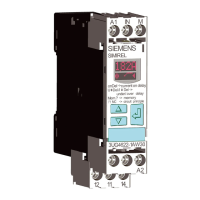
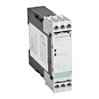
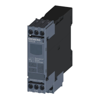
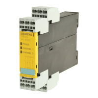
1)
Information on setting accuracy
• at setting value "0", a setting accuracy of >15 % applies for R
• at setting value ">1", a setting accuracy of 6 % applies for R
You can nd additional information on the connection terminals and the permissible conductor
cross-sections in the Chapter "Technical data (Page 201)".
You can nd information on connecting in the Chapter "Circuit diagrams (Page 192)".
9.4.2 Functions
General functionality
The 3UG4582/3UG4583 insulation monitoring relays are supplied with a rated control and
supply voltage of 24 V to 240 V AC/DC, and they monitor the insulation resistance in accordance
with IEC 61557‑8 in ungrounded IT-AC systems, IT‑AC systems with galvanically connected DC
circuits, or IT‑DC systems.
The devices can monitor control circuits (1-phase) and main circuits (3-phase). For this purpose,
the insulation resistance between power supply cords (terminal: L+ and L-) and the ground of the
system (terminal
and KE) is measured. Systems with rated system voltages U
n
= 0 to
250 V AC (15 to 400 Hz) / U
n
= 0 to 300 V DC (3UG4582) or U
n
= 0 to 400 V AC (15 to 400 Hz) /
U
n
= 0 to 600 V DC (3UG4583) can be connected direct to the measuring inputs, and their
insulation resistance can be monitored.
The insulation monitoring relays have two rotary buttons (3UG4582)/four rotary buttons
(3UG4583) for adjusting the insulation resistance R and a Test/RESET button, to perform an
internal test on the device or to reset the device.
If the measured value drops below the set threshold, the output relays are set to fault status.
For systems with voltages over 400 V AC and 600 V DC, the 3UG4583 insulation monitoring
relays with 3UG4983 voltage reducer module can be used for extending the voltage range.
You will nd the adjustment ranges and factory settings of the available parameters in Chapter
"Operator control (Page 188)".
You will nd a description of the individual parameters in the Chapter "Parameters (Page 281)".
Measuring method
The 3UG4582/3UG4583 insulation monitoring relays use a new predictive measuring method
for high-speed measurements and fast pick-up times. The devices can be congured to the
relevant application conditions and are therefore versatile in use.
A pulsing measuring signal is fed into the system to be monitored and the insulation resistance
is calculated from this.
The received signal is dierent in form to the injected measuring signal. This change depends on
the insulation resistance and the system discharge capacity. The change to the insulation
resistance is predicted from this deviating form. If the predicted insulation resistance
3UG458. insulation monitoring relay.
9.4 3UG4582/3UG4583 insulation monitoring relays
SIRIUS 3UG4 / 3RR2 monitoring relay
178 Equipment Manual, 07/2021, NEB927043002000/RS-AD/005
 Loading...

