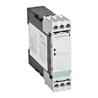
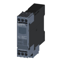
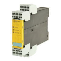
12.3 Functions
General functionality
Depending on the setting, the speed monitoring relays monitor a speed in revolutions per
minute (rpm) for overshoot (rpm▲), undershoot (rpm▼) or in range monitoring (rpm▲ and
rpm▼). Depending on their design, the devices are powered with a rated control supply voltage
of 24 V AC/DC or 24 to 240 V AC/DC supply voltage through terminals A1/A2.
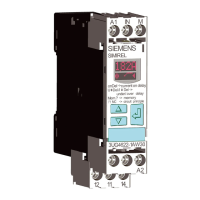
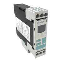
The 3UG4651 speed monitoring relays have a display and are parameterized with three keys.
You will nd the adjustment ranges and factory settings of the available parameters in Chapter
"Operation (Page 234)".
You can nd a description of the individual parameters in Chapter "Parameters (Page 281)".
Speed monitoring functions according to the principle of period duration measurement.
In the speed monitoring relay, the time interval between two consecutive rising edges of the
pulse encoder is measured and compared with the minimum and/or maximum permissible
period duration calculated from the set threshold values for the speed. Period duration
measurement detects a speed deviation after only two pulses.
By using up to ten pulse encoders distributed simultaneously across the range, the period
duration, and thus the response time, can be reduced. By taking account of the number of
sensors in the speed monitoring relay, the speed continues to be displayed in revolutions per
minute.
The number of pulses supplied by the pulse encoder can be dened with the help of entering a
scaling value (Scale). This allows the revolutions per minute to be read direct on the display.
The speed monitoring relays have two dierent pulse inputs. Only one of these may be used! A
pnp‑switching three-wire sensor for 0 V / +24 V DC pulses can be connected at terminal IN1. It
is supplied from the output relay via terminals 0V and 24V / with up to 50 mA. Use of a
mechanical pulse contact with an external DC supply of 4.5 to 30 V is also permissible at terminal
IN1.
Note
To detect the edges reliably, the pulses and pauses between pulses of the pulse encoders used
must be applied for at least 5 ms. A pause is detected at voltage level < 1 V. A pulse requires a
minimum value of 4.5 V.
Alternatively, a two-wire NAMUR sensor supplied from terminal 8V2, or a mechanical contact,
can be connected at terminal IN2.
Monitoring
Startup delay
To be able to start a drive, the output relay switches to the correct state during the ON-delay time
(onDel) depending on the selected open-circuit principle or closed-circuit principle, even if the
measured value is still under the set value.
3UG4651 speed monitoring relay
12.3 Functions
SIRIUS 3UG4 / 3RR2 monitoring relay
Equipment Manual, 07/2021, NEB927043002000/RS-AD/005 231
 Loading...

