6.7 3UG4617 / 3UG4618 line monitoring relays
6.7.1 Operator controls and connection terminals
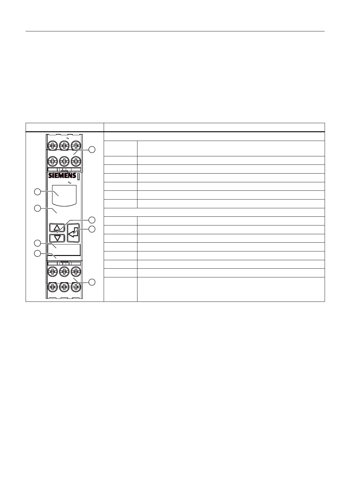
Front view / terminal labeling 3UG4617 / 3UG4618
Front view Description
Del -> Umin/Umax/
Asym delay
Mem ? -> Memory?
3/N 90-400V
N
24
2122
12
14
11
L3
L2
L1
3UG4618-....
SIRIUS
3 160-690V
Position digits
① Terminal block (removable):
Connection is possible using screw terminals or spring-loaded terminals.
② Arrow keys for menu navigation
③ SET key for menu navigation
④ Device article number
⑤ Label
⑥ Legend for menu
⑦ Display for parameterization, actual-value indication, and diagnostics
Terminal labels
L1, L2, L3 Rated control supply voltage
N Neutral conductor (on 3UG4618 only)
12 Output relay K1 CO contact NC contact
11 Output relay K1 CO contact root
14 Output relay K1 CO contact NO contact
22 Output relay K2 CO contact NC contact
21 Output relay K2 CO contact root
24 Output relay K2 CO contact NO contact
You can nd additional information on the connection terminals and the permissible conductor
cross-sections in the Chapter "Connection methods (Page 23)".
You can nd information on connecting in the Chapter "Circuit diagrams (Page 119)".
3UG4.1 line monitoring relay
6.7 3UG4617 / 3UG4618 line monitoring relays
SIRIUS 3UG4 / 3RR2 monitoring relay
112 Equipment Manual, 07/2021, NEB927043002000/RS-AD/005
 Loading...