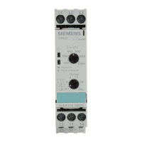
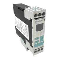
9.4 3UG4582/3UG4583 insulation monitoring relays
9.4.1 Operator controls and connection terminals
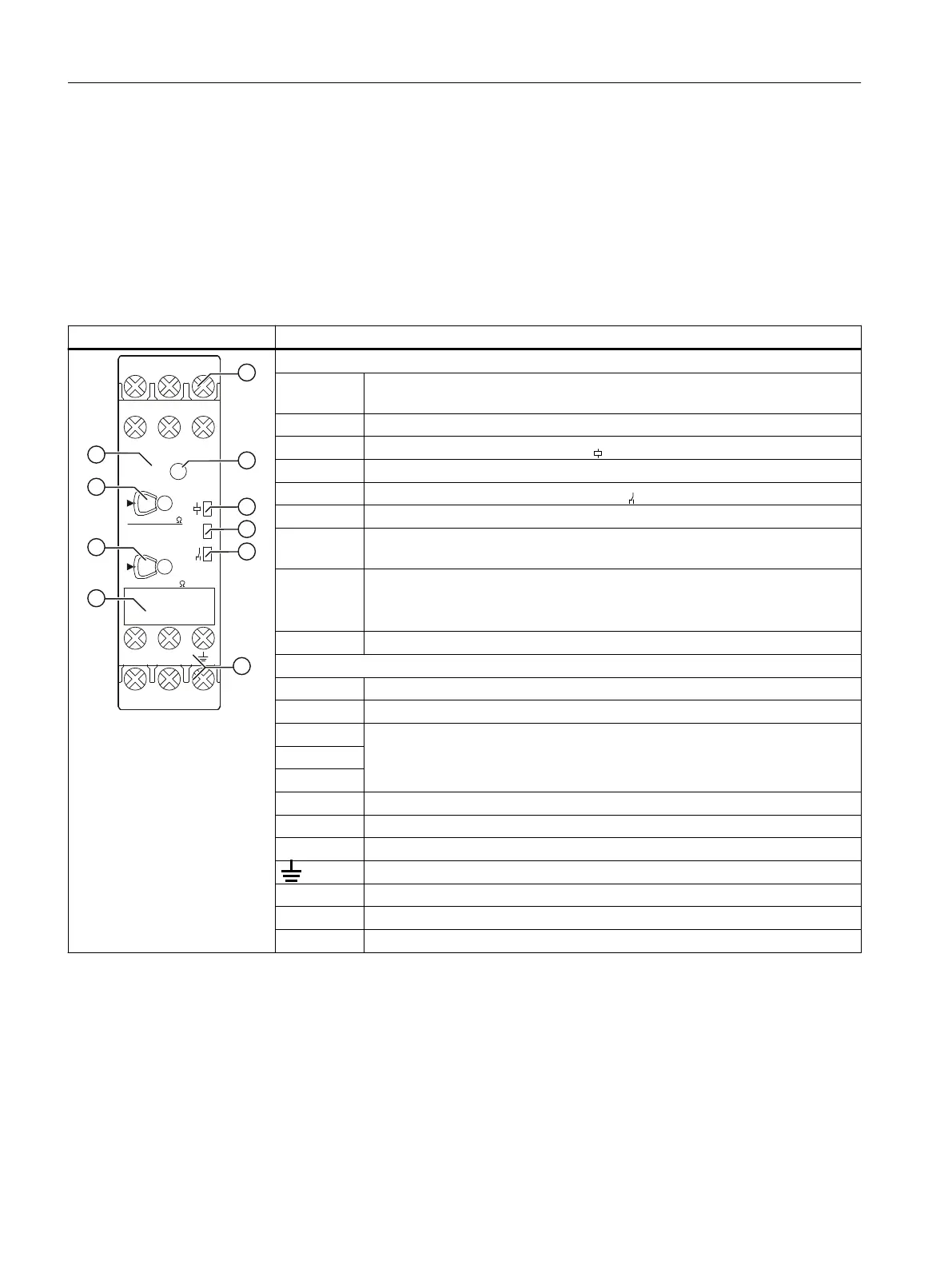
Front view/terminal labeling 3UG4582-1AW30
Front view Description
8*
$:
/
/
$
7HVW
5HVHW
N5YDOXH
5 55
5YDOXH
(.$
<<<
N
)
s
Position digits
① Terminal block:
Screw-type connections are possible.
② Test/RESET button
③ Status display: LED for device status (green)
④ Status display: LED for monitoring status F (red)
⑤ Status display: LED output contact status (yellow)
⑥ Label
⑦ Rotary knob for adjusting the insulation resistance (R.2 for the units position of
R)
⑧ Rotary knob for adjusting the insulation resistance (R.1 for the tens position of
R)
Setting value "0" is colored yellow.
1)
⑨ Device article number
Terminal labels
A1+ Rated control supply voltage ∼ / +
A2- Rated control supply voltage ∼ / -
Y1 Control inputs; isolation control
Y1-Y3: Remote test
Y2-Y3: Remote reset/autoreset
Y2
Y3
L+ Measuring signal input, connection to phase or L+
L- Measuring signal input, connection to phase, N conductor or L-
KE Measuring signal input, control ground connection for open-circuit monitoring
Measured signal input, grounding connection
12 Output relay K1 CO contact NC contact
11 Output relay K1 CO contact root
14 Output relay K1 CO contact NO contact
1)
Information on setting accuracy
• at setting value "0", a setting accuracy of >15 % applies for R
• at setting value ">1", a setting accuracy of 8 % applies for R
You can nd additional information on the connection terminals and the permissible conductor
cross-sections in the Chapter "Technical data (Page 201)".
You can nd information on connecting in the Chapter "Circuit diagrams (Page 192)".
3UG458. insulation monitoring relay.
9.4 3UG4582/3UG4583 insulation monitoring relays
SIRIUS 3UG4 / 3RR2 monitoring relay
170 Equipment Manual, 07/2021, NEB927043002000/RS-AD/005
 Loading...