Labeling Function Connection pin
Exc- Supply load cell - 6
Exc+ Supply load cell + 5
6.2.1 Connecting SIWAREX JB to the electronic weighing system and load cell
Procedure
1. Open the cover of the SIWAREX JB.
2. Screw in an M16 x 1.5 cable gland for each load cell.
3. Screw in an M20 x 1.5 EMC cable gland for the signal cable to the electronic weighing
system.
4. Wire the SIWAREX JB to the load cell and the electronic weighing system in accordance
with Wiring diagrams (Page 28).
To learn how to connect the cable, see section Connecting the cable (Page 31).
5. Close any unused opening in the enclosure with a blanking plug.
6. Connect the equipotential bonding conductor to the outside of the enclosure.
Use shielded cable lugs.
7. Close the cover of the SIWAREX JB according to the tightening torque.
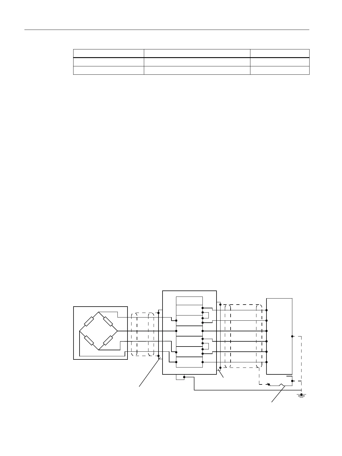
6.2.2 Wiring diagrams
6.2.2.1 Load cells with four-wire system
&DEOHJODQG
&DEOHJODQG
6VKLHOGVXSSRUWHOHPHQW
-XQFWLRQER[
6LJQDOFDEOH
(OHFWURQLF:HLJKLQJ6\VWHP
/RDGFHOO
%ODFN
*UD\
5HG
%OXH
*UHHQ
:KLWH
3$/
SIGNAL-
EXC-
SENSE-
SHIELD
EXC+
SENSE+
SIGNAL+
SIGNAL+
SENSE+
EXC+
SIGNAL-
SENSE-
EXC-
Connecting
6.2 Connection of analog load cells
SIWAREX WP321
28 Operating Instructions, 08/2019, A5E33715669A-AD

 Loading...