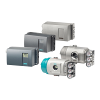
Variable Note Type L Rw De‐
fault
Min. Max.
7009 Standstill range / standstill wait time not
plausible
BIT r 0 0 1
7010 Scale interval / rounding not plausible BIT r 0 0 1
7011 Filter parameter not plausible BIT r 0 0 1
7014 Time input not plausible BIT r 0 0 1
Reserve - BIT r 0 0 1
Reserve - BIT r 0 0 1
7019 RS485 parameter error BIT r 0 0 1
Reserve - UINT 2 r 0 - -
Reserve - UINT 2 r 0 - -
Reserve - UINT 2 r 0 - -
8.16.1 Error bytes 0 to 7
In these areas, messages are represented by bits. A set bit means that the corresponding
message is activated. The message bit is set following a data or operator error and
automatically reset approximately 3 seconds later.
Message bits are analyzed by the operator panel message system.
The data/operator errors (error numbers 1xxx) are present in the first two bytes. These are
followed by two bytes with technology errors (error numbers 2xxx) and six bytes with data and
operator errors (error numbers 5xxx and 7xxx).
8.17 DR 34 ASCII main display value
The ASCII weight corresponds to the value on the main display of the scales and can be used
for a supplementary display as well as the main display.
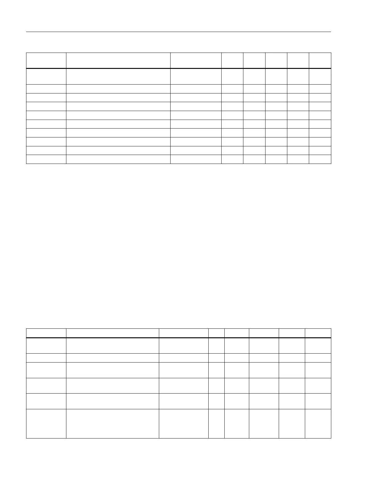
Table 8-14 Assignment of data record 34
Variable Note Type L Rw Default Min. Max.
Data record
number
Contains no. of data record UINT 2 r 34 - -
Length Data record length information UINT 2 r 26 - -
Application Information about which application
the DR belongs to
UINT 2 r 201 - -
Version identi‐
fier
Information on the current data re‐
cord version
UINT 2 r 1 1 65635
ASCII display
string header
Maximum length and actual length
of string
UBYTE[2] 2 r 16,2 - -
Content of
main display
as ACII string
(Page 91)
For display of the weight value and
other current values (see below)
STRING[16] 16 r " " - -
Scale parameters and functions
8.17 DR 34 ASCII main display value
SIWAREX WP321
90 Operating Instructions, 08/2019, A5E33715669A-AD

 Loading...