7-50
DSR-2000A/2000AP
7-17. Loading Motor Replacement
Outline
Replacement
Disconnecting the connector
Replacing the loading motor assembly
Reconnecting the connector
Preparation
1. Set the unit to the unthreading end status.
2. Power off the unit.
3. Remove the top panel. (Refer to Section 3-3.)
4. Remove the cassette compartment. (Refer to Section 3-4.)
Tools
. Torque screwdriver’s bit (for M1.4) : J-6325-110-A
. Torque screwdriver (for 3 kgf.cm) : J-6325-400-A
. Tweezers
Replacement
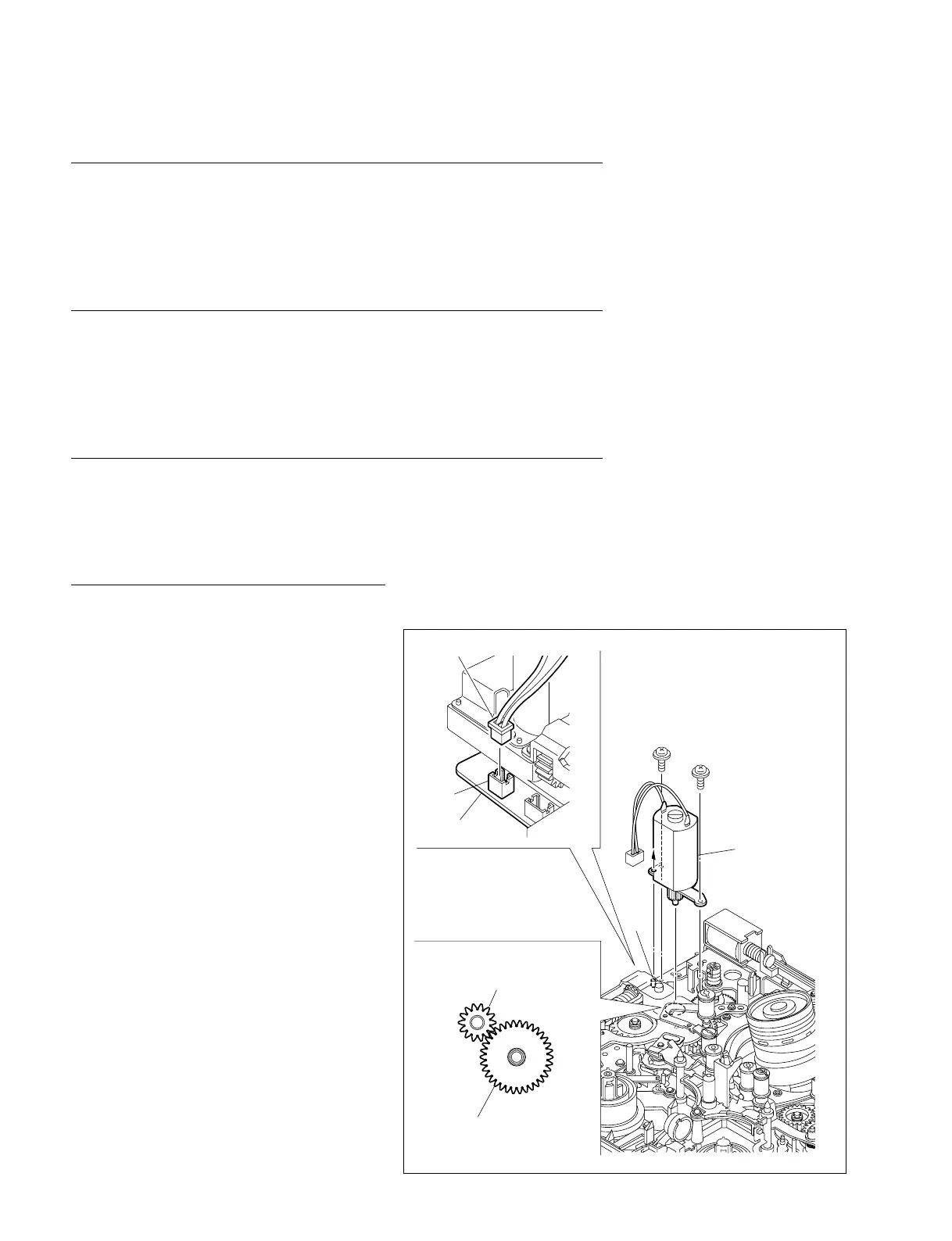
1. Disconnecting the connector
Disconnect the harness from the connector
(CN19) on the MS-64 board with tweezers.
2. Replacing the loading motor assembly
(1) Remove the two screws to remove the
loading motor assembly.
(2) Align a positioning hole in a new loading
motor with the positioning pin on the MD
chassis and engage the motor gear with the
FG gear.
(3) Fix the loading motor assembly with the two
screws.
Tightening Torque : 0.1 N.m {1 kgf.cm}
3. Reconnecting the connector
Reconnect the harness to the connector (CN19)
on the MS-64 board with tweezers.
P1.4 x 3.5
P1.4 x 3.5
Loading motor
assembly
Pin
MS-64 board
CN19
Harness
Motor gear
FG gear assembly
 Loading...