8-6
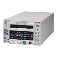
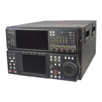
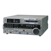
DSR-2000A/2000AP
8-2. Tape Path Adjustment
Basic knowledge
To perform the tracking adjustment using the alignment tape (XH2-1AST), refer
the following items.
. For the procedure to enter the maintenance menu, refer to Section 5-2-2.
. For the procedure to exit the maintenance menu, refer to Section 5-2-3.
. For the operating procedure of the maintenance menu during the tracking adjust-
ment, refer to Section 8-1.
Tools
. Alignment tape, XH2-1AST : 8-967-999-02
. Tape path adjustment board, DJ-461 : J-6444-610-B
. Dual trace oscilloscope
Check procedure
1. Connect the oscilloscope as follows :
CH-1 : TP2 / DJ-461
CH-2 : TP3 / DJ-461
TRIG : CH-2
2. Insert the alignment tape XH2-1AST on the VTR.
3. Put the unit into PLAY mode.
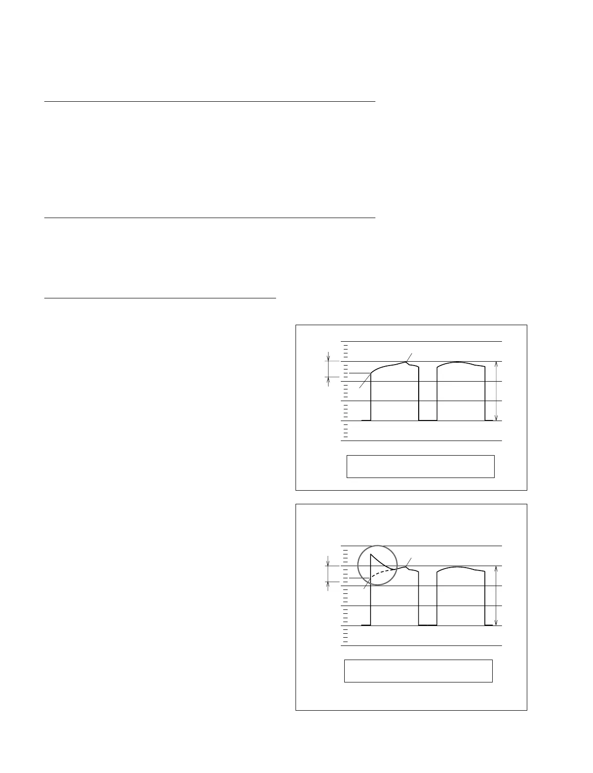
4. Adjust the variable VOLTS/DIV control of the
oscilloscope so that the maximum amplitude of the RF
waveform becomes the three DIVISIONs on the
oscilloscope.
4/5 Div
max.
min.
3 Div
Specification : max. _ min. < 4/5 Div
max.
3 Div
min.
4/5 Div
Fig.1
Specification : max. _ min. < 4/5 Div
2
Guide S2
Entrance side
Exit side
5. Adjust the RF waveform until it satisfies the specifica-
tion by changing the height of the S2 and T2 guides.
. When the RF waveform at the entrance side forms
the shape of the solid line shown in Fig.1, turn the
guide S2 clockwise to obtain the flat waveform.
n
This adjustment must end with the clockwise
rotation of the guide S2
 Loading...