

C
Christopher ParsonsAug 20, 2025
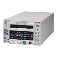
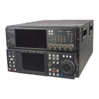
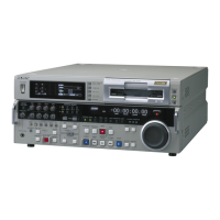
Why is recording not possible on my Sony DSR-2000AP DVR?
- SstephenrobertsAug 20, 2025
Recording may not be possible on your Sony DVR if the cassette's REC/SAVE switch is set to SAVE. To resolve this, set the REC/SAVE switch to REC, or use another cassette. Another reason could be that the REC INHIBIT switch on the subsidiary control panel is set to ON. In this case, set the REC INHIBIT switch on the subsidiary control panel to OFF.