ENGINE GENERAL INFORMATION AND DIAGNOSIS (H27 ENGINE) 6-1-45
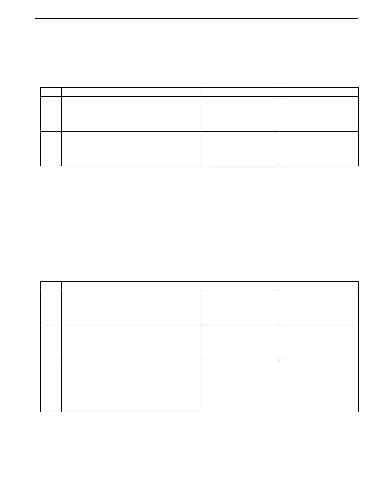
Table A-3 Malfunction Indicator Lamp Check – MIL Flashes at Ignition Switch
ON (Vehicle with Monitor Connector)
WIRING DIAGRAM/CIRCUIT DESCRIPTION
Refer to TABLE A-1.
TROUBLESHOOTING
Table A-4 Malfunction Indicator Lamp Check – MIL Does Not Flash or Just
Remains ON Even with Grounding Diagnosis Switch Terminal (Vehicle with
Monitor Connector)
WIRING DIAGRAM/CIRCUIT DESCRIPTION
Refer to TABLE A-1.
TROUBLESHOOTING
Step Action Yes No
1 MIL Flashing Pattern check:
1) Turn ignition switch ON.
Does lamp flashing pattern indicate diagnostic
trouble code?
Go to Step 2. Go to “Diagnosis” in Sec-
tion 8G.
2 Diag. Switch Circuit check:
Is diag. switch terminal connected to ground via
service wire?
System is in good condi-
tion.
“YEL” circuit shorted to
ground. If circuit is OK
substitute a known-good
ECM (PCM) and recheck.
Step Action Yes No
1 MIL Circuit check:
1) Turn ignition switch OFF and disconnect
connectors from ECM (PCM).
Does MIL turn ON at ignition switch ON?
“PPL/YEL” circuit shorted
to ground.
Go to Step 2.
2 ECM (PCM) Connection check:
1) Turn ignition switch OFF.
Is connector (E61-29 connection) connected to
ECM (PCM) properly?
Go to Step 3. Poor connector connec-
tion.
3 Diag. switch Terminal Circuit check:
1) Connect connectors to ECM (PCM).
2) Using service wire, ground E61-29 terminal
with connectors connected to ECM (PCM).
3) Turn ignition switch ON.
Does MIL flash?
“YEL” or “BLK” circuit
open.
Substitute a known-good
ECM (PCM) and recheck.

 Loading...


