6E2-42 ENGINE AND EMISSION CONTROL SYSTEM (SEQUENTIAL MULTIPORT FUEL INJECTION FOR H27 ENGINE)
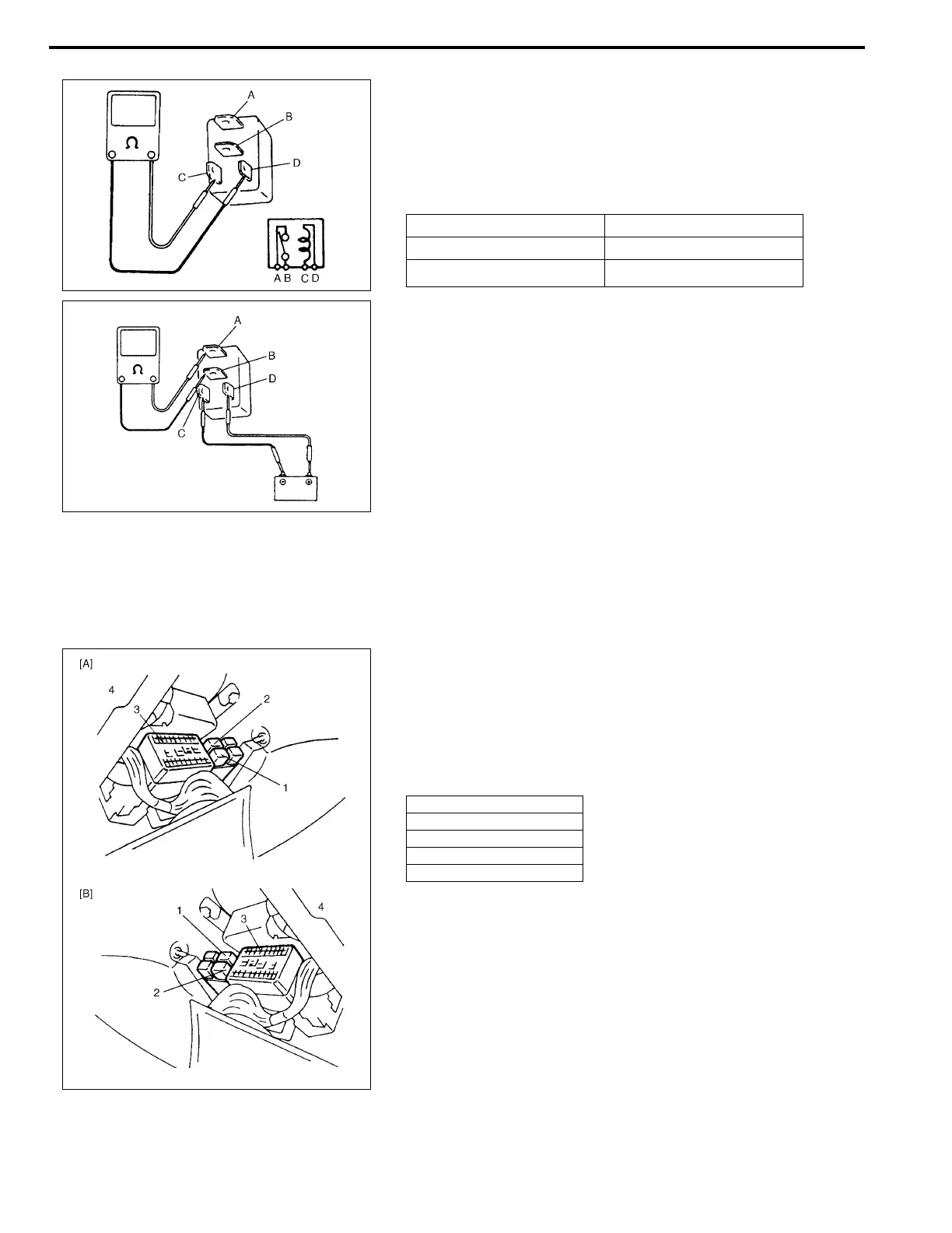
3) Check resistance between each two terminals as in table
below.
If check results are as specified, proceed to next operation
check. If not, replace.
Main relay resistance:
4) Check that there is continuity between terminals “A” and “B”
when battery is connected to terminals “C” and “D”.
If malfunction is found, replace.
Fuel pump relay
INSPECTION
1) Disconnect negative (–) cable at battery.
2) Remove fuel pump relay (2) from connector.
3) Structure of fuel pump relay is the same as that of main
relay.
Check its resistance and operation using the same proce-
dure as that for main relay.
If malfunction is found, replace.
TERMINALS RESISTANCE
Between “A” and “B” ∞
∞∞
∞ (Infinity)
Between “C” and “D”
79 – 95 Ω
ΩΩ
Ω (at 20
°
C (68
°
F))
1. Main relay
3. Fuse box
4. Instrument panel
[A]: Left-hand steering vehicle
[B]: Right-hand steering vehicle