ENGINE GENERAL INFORMATION AND DIAGNOSIS (H27 ENGINE) 6-1-115
DTC P1510 Ecm Back-Up Power Supply Malfunction
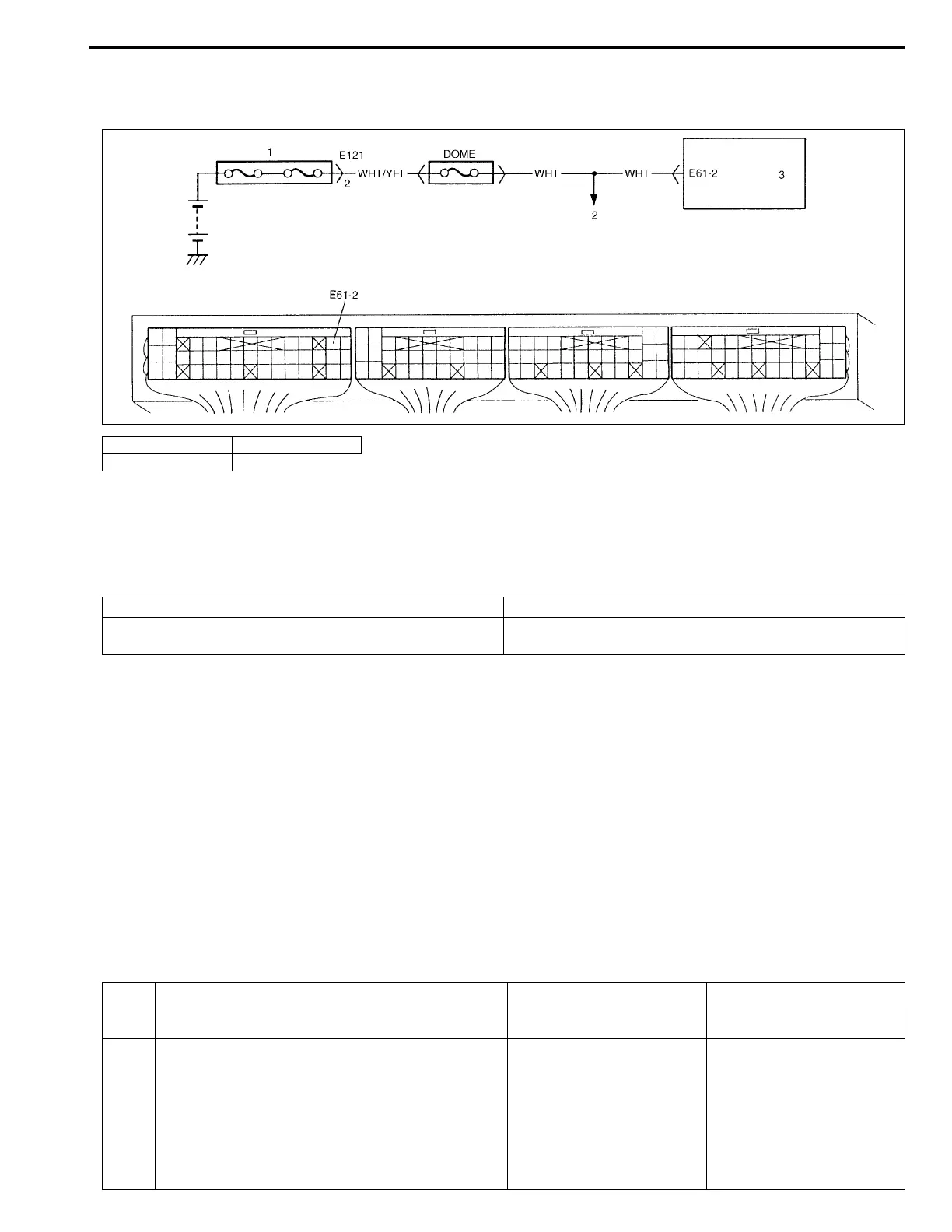
WIRING DIAGRAM
CIRCUIT DESCRIPTION
Battery voltage is supplied to keep DTC memory, values that ECM has learned to control engine, etc. in ECM
even when ignition switch is turned OFF.
DTC DETECTING CONDITION AND TROUBLE AREA
DTC CONFIRMATION PROCEDURE
1) Connect scan tool to DLC with ignition switch OFF.
2) Turn ON ignition switch and clear DTC, pending DTC and freeze frame data by using scan tool and run
engine at idle speed for 1min.
3) Check DTC by using scan tool.
TROUBLESHOOTING
1. Main fuse box 3. ECM (PCM)
2. To DLC
DTC DETECTING CONDITION TROUBLE AREA
Back-up circuit voltage lower than specification is detected
while engine is running.
• ECM (PCM) back-up circuit
• ECM (PCM)
NOTE:
Check to make sure that following condition is satisfied when using this “DTC CONFIRMATION PRO-
CEDURE”.
• Intake air temp. : – 8°C (18°F) or higher
• Engine coolant temp. : – 8 – 110°C (18 – 230°F)
• Altitude (barometric pressure) : 2400 m, 8000 ft or less (560 mmHg (75 kPa) or more)
Step Action Yes No
1Was “ENGINE DIAG. FLOW TABLE” performed? Go to Step 2. Go to “ENGINE DIAG. FLOW
TABLE” in this section.
2 Battery voltage supply circuit check :
1) Remove ECM (PCM) cover.
2) While engine running, check voltage between E61-
2 and ground.
Is voltage 10 – 14 V?
Poor E61-2 connection or
intermittent trouble.
Check for intermittent referring
to “INTERMITTENT AND
POOR CONNECTION” in
Section 0A.
If wire and connections are
OK, substitute a known-good
ECM (PCM) and recheck.
“WHT” circuit open or short.