6-1-94 ENGINE GENERAL INFORMATION AND DIAGNOSIS (H27 ENGINE)
DTC P0420 Catalyst System Efficiency Below Threshold (Bank 1)
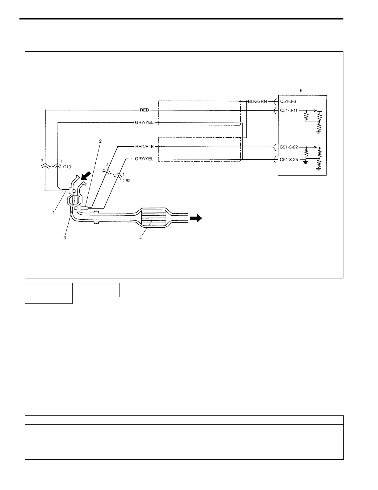
SYSTEM DIAGRAM
CIRCUIT DESCRIPTION
Exhaust oxygen concentration at the pre-catalyst and the post-catalyst of WU-TWC is detected from HO2S-1
and HO2S-2 respectively and accordingly ECM (PCM) controls the closed loop which then controls the fuel
injection volume. (Refer to Section 6E2.) While the above control is going on and if WU-TWC is in good condi-
tion, the output voltage of HO2S-2 is maintained at specified level. As WU-TWC becomes deteriorated, even
when the above control is going on, the exhaust gas which has passed WU-TWC then passes HO2S-2 at the
exhaust oxygen concentration similar to that of the pre-catalyst without being oxygenated or converted. Thus,
waveforms of HO2S-1 and HO2S-2 output voltages become alike. ECM (PCM) judges deterioration of WU-TWC
by comparing waveforms of HO2S-1 and HO2S-2.
DTC DETECTING CONDITION AND TROUBLE AREA
1. HO2S-1 (Bank-1) 4. TWC
2. HO2S-2 (Bank-1) 5. ECM (PCM)
3. WU-TWC
DTC DETECTING CONDITION TROUBLE AREA
While running under conditions described for DTC CON-
FIRMATION PROCEDURE, output waveform of HO2S-1
becomes similar to that of HO2S-2.
(2 driving cycle detection logic)
• Exhaust gas leakage
• Warm up three way catalytic converter
• Heated oxygen sensor – 2 or its circuit
•ECM (PCM)

 Loading...


