8E-12 CRUISE CONTROL SYSTEM
Stop Lamp Switch (with Pedal Position Switch) Circuits Check
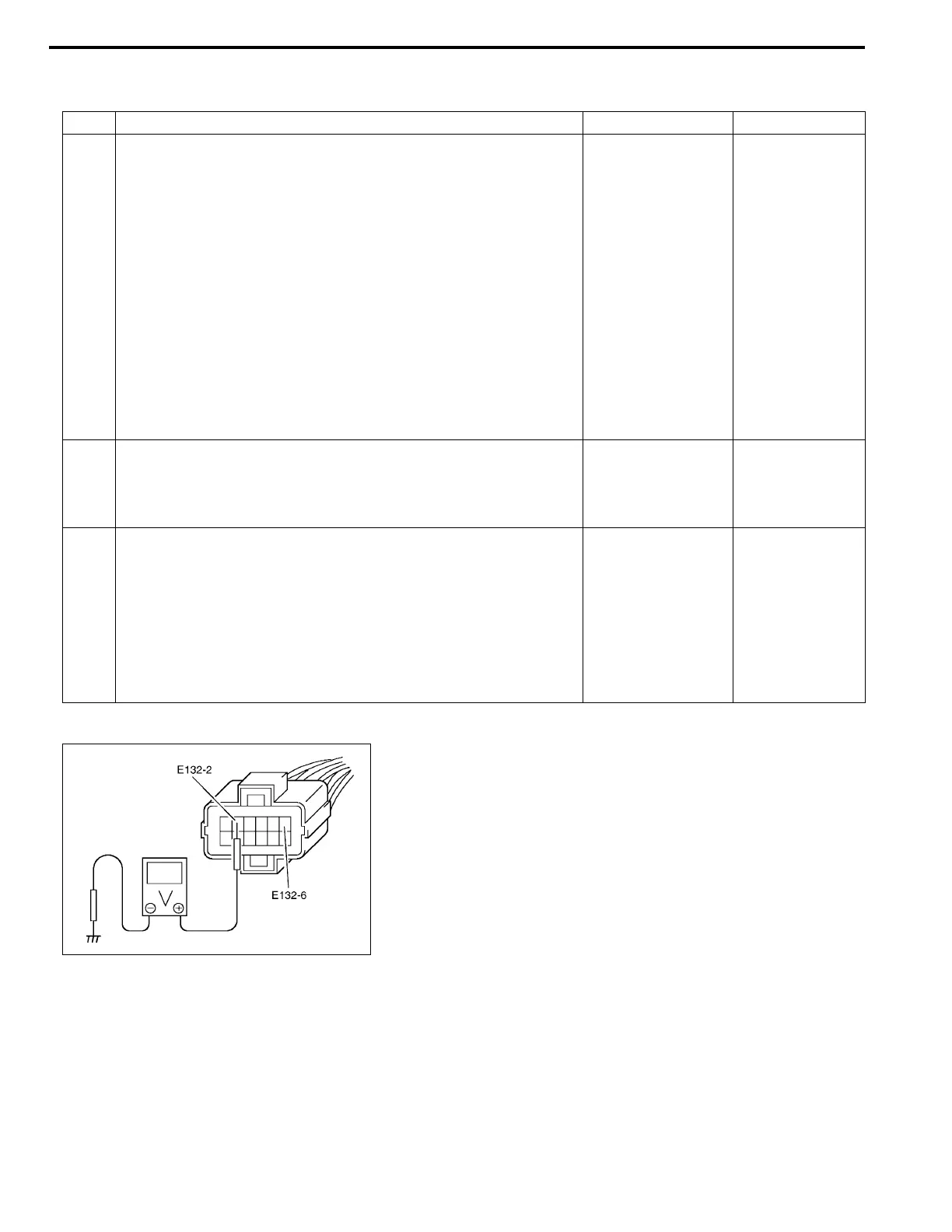
Fig. for Step 1
Step Action Yes No
1 Stop Lamp Switch (With Pedal Position Switch) Circuits Check
1) Disconnect connector from cruise control module with
ignition switch OFF.
2) Check for proper connection to cruise control module at
terminals E132-2 and E132-6.
3) If OK, turn ignition switch ON.
4) Check Voltage between each terminal and ground under
each condition below.
Stop lamp switch circuit specification
Brake pedal released terminal E132-2 : 0 V
Brake pedal released terminal E132-6 : 10 – 14 V
Brake pedal depressed terminal E132-2 : 10 – 14 V
Brake pedal depressed terminal E132-6 : 0 V
Is check result satisfactory?
Stop lamp switch
(with pedal position
switch) circuits are
OK.
Go to Step 2.
2 Stop Lamp Switch Position Check
1) Check stop lamp switch for installation position referring to
“STOP LAMP SWITCH” in Section 5.
Is check result satisfactory?
Go to Step 3. Adjust.
3 Stop Lamp Switch (With Pedal Position Switch) Check
1) Disconnect connector from stop lamp switch.
2) Check for proper connection to stop lamp switch at all ter-
minals.
3) If OK, check stop lamp and pedal position switches for
operation referring to “STOP LAMP SWITCH” in this sec-
tion.
Is this switch in good condition?
“YEL/GRN” or
“GRN/WHT” circuit
is open or short.
Replace.

 Loading...


