6E2-8 ENGINE AND EMISSION CONTROL SYSTEM (SEQUENTIAL MULTIPORT FUEL INJECTION FOR H27 ENGINE)
Electronic Control System
The electronic control system consists of 1) various sensors which detect the state of engine and driving condi-
tions, 2) ECM (PCM) which controls various devices according to the signals from the sensors and 3) various
controlled devices.
Functionally, it is divided into the following sub systems:
• Fuel injection control system
• Heated oxygen sensor heater control system (if equipped)
• Idle air control system
• Fuel pump control system
• Evaporative emission control system
• Ignition control system
• EGR system (if equipped)
Also, with A/T model, PCM controls A/T.
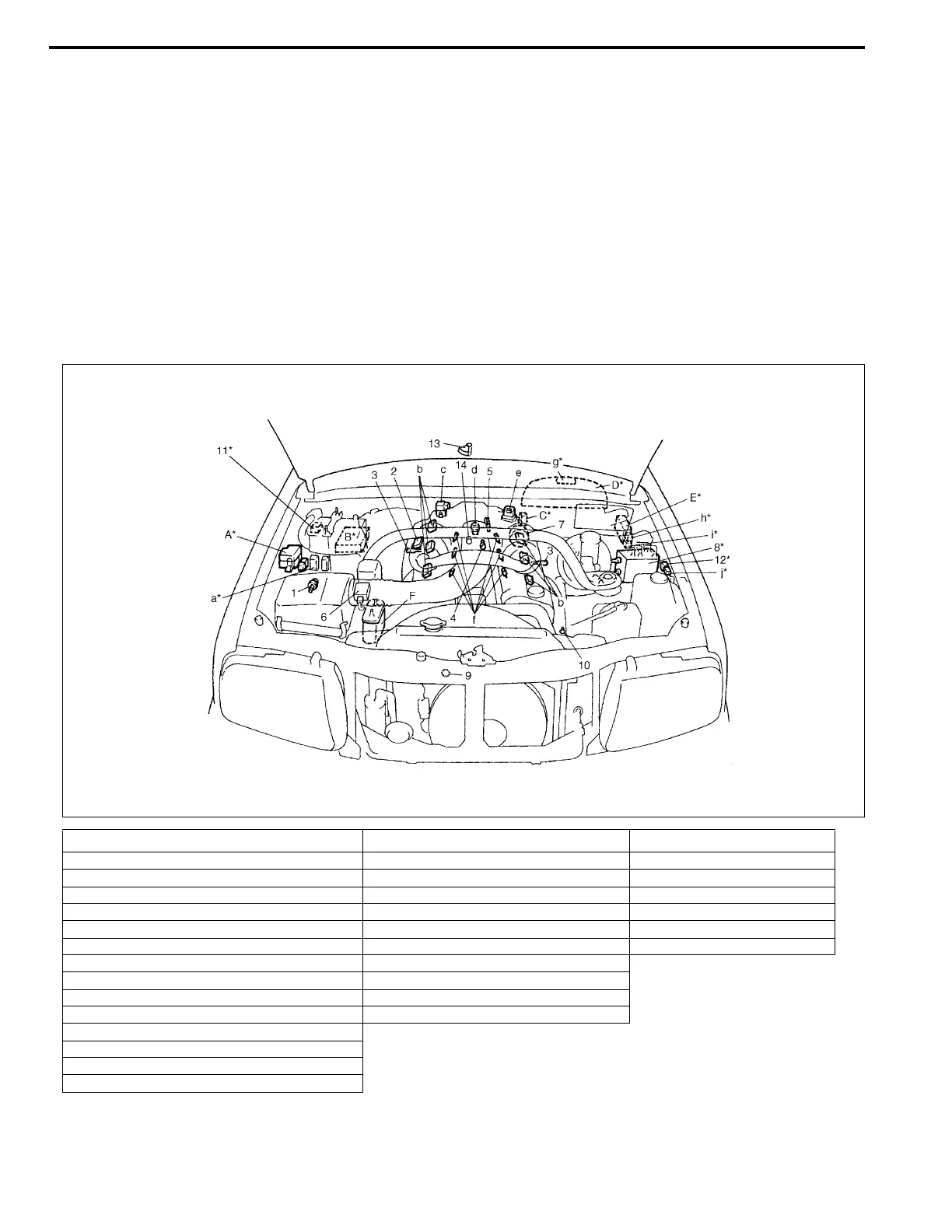
INFORMATION SENSORS CONTROLLED DEVICES OTHERS
1. IAT sensor a : A/C condenser fan motor relay (if equipped) A : Main fuse box
2. MAP sensor (if equipped) b : Ignition coil assemblies B : ECM (PCM)
3. Heated oxygen sensor (sensor 1) (if equipped) c : EVAP canister purge valve C : Data link connector
4. ECT sensor d : EGR valve (if equipped) D : Combination meter
5. TP sensor e : Idle air control valve E : Fuse box
6. MAF sensor f : Injectors F : EVAP canister
7. Camshaft position sensor (CMP sensor) g : Malfunction indicator lamp
8. ABS control module h : Fuel pump relay
9. Crankshaft position sensor (CKP sensor) (if equipped) i : Main relay
10. Power steering pressure switch (PSP switch) j : Oxygen sensor heater relay (if equipped)
11. CO adjusting resistor (if equipped)
12. Monitor connector (if equipped)
13. Transmission range switch (A/T)
14. Knock sensor
NOTE:
Above figure shows left-hand steering vehicle. For right-hand steering vehicle, parts with (*) are
installed at the side of symmetry.

 Loading...


