DIFFERENTIAL (REAR) 7F-13
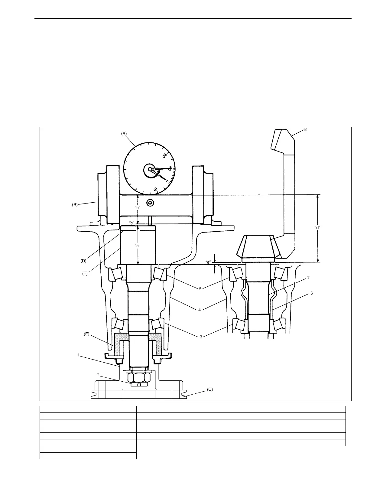
Drive bevel pinion
To engage drive bevel pinion and gear correctly, it is pre-required to install drive bevel pinion to differential carrier
properly by using adjusting shim as described on the followings. Shown below is relative positions of drive bevel
pinion, differential carrier and mounting dummy.
Special tool
(A) : 09900-20606
(B) : 09926-78320
(C) : 09922-75222
(D) : 09922-76570
(E) : 09951-46010
(F) : 09926-78311-002
1. Universal Joint flange (P/No. 27110-60A00) “a”: Pinion dummy height + Attachment height
2. Nut “b”: Axle dummy radius
3. Front bearing “a” + “b” Mounting dummy size 110.00 mm/4.3307 in.
4. Differential carrier “c”: Measured dimension
5. Rear bearing “d”: Drive bevel pinion mounting distance 110.00 mm/4.3307 in.
6. Spacer “e”: Shim size for mounting distance adjustment (= “c”)
7. Drive bevel pinion
8. Drive bevel gear

 Loading...


