ENGINE AND EMISSION CONTROL SYSTEM (SEQUENTIAL MULTIPORT FUEL INJECTION FOR H27 ENGINE) 6E2-35
Throttle position sensor (TP sensor)
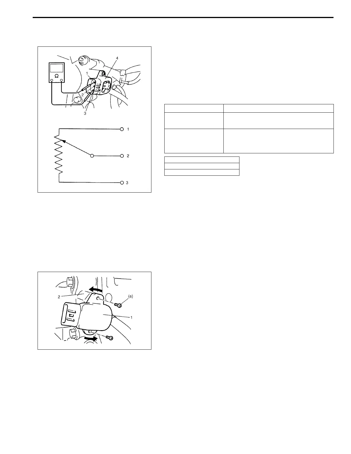
INSPECTION
1) Disconnect negative (–) cable at battery and coupler from TP
sensor (4).
2) Using ohmmeter, check resistance between terminals under
each condition given in table below.
If check result is not satisfactory, replace TP sensor.
TP sensor specification:
3) Connect TP sensor coupler securely.
4) Connect negative cable to battery.
REMOVAL
1) Disconnect negative (–) cable at battery.
2) Disconnect coupler from TP sensor.
3) Remove TP sensor from throttle body.
INSTALLATION
1) Install TP sensor (1) to throttle body (2).
Fit TP sensor (1) to throttle body (2) in such way that its
holes are a little away from TP sensor screw holes as shown
in the figure and turn TP sensor (1) clockwise so that those
holes align.
Tightening torque
TP sensor screw
(a) : 3.5 N·m (0.35 kg-m, 2.5 lb-ft)
2) Connect coupler to TP sensor securely.
3) Connect battery negative (–) cable to battery.
TERMINALS RESISTANCE
Between 1 and
3 terminals
4.0 – 6.0 kΩ
ΩΩ
Ω
Between 1 and
2 terminals
0.02 – 6.0 kΩ
ΩΩ
Ω
varying linearly according to
throttle valve opening
1. Ground terminal
2. Output voltage terminal
3. Reference voltage terminal

 Loading...


