7F-6 DIFFERENTIAL (REAR)
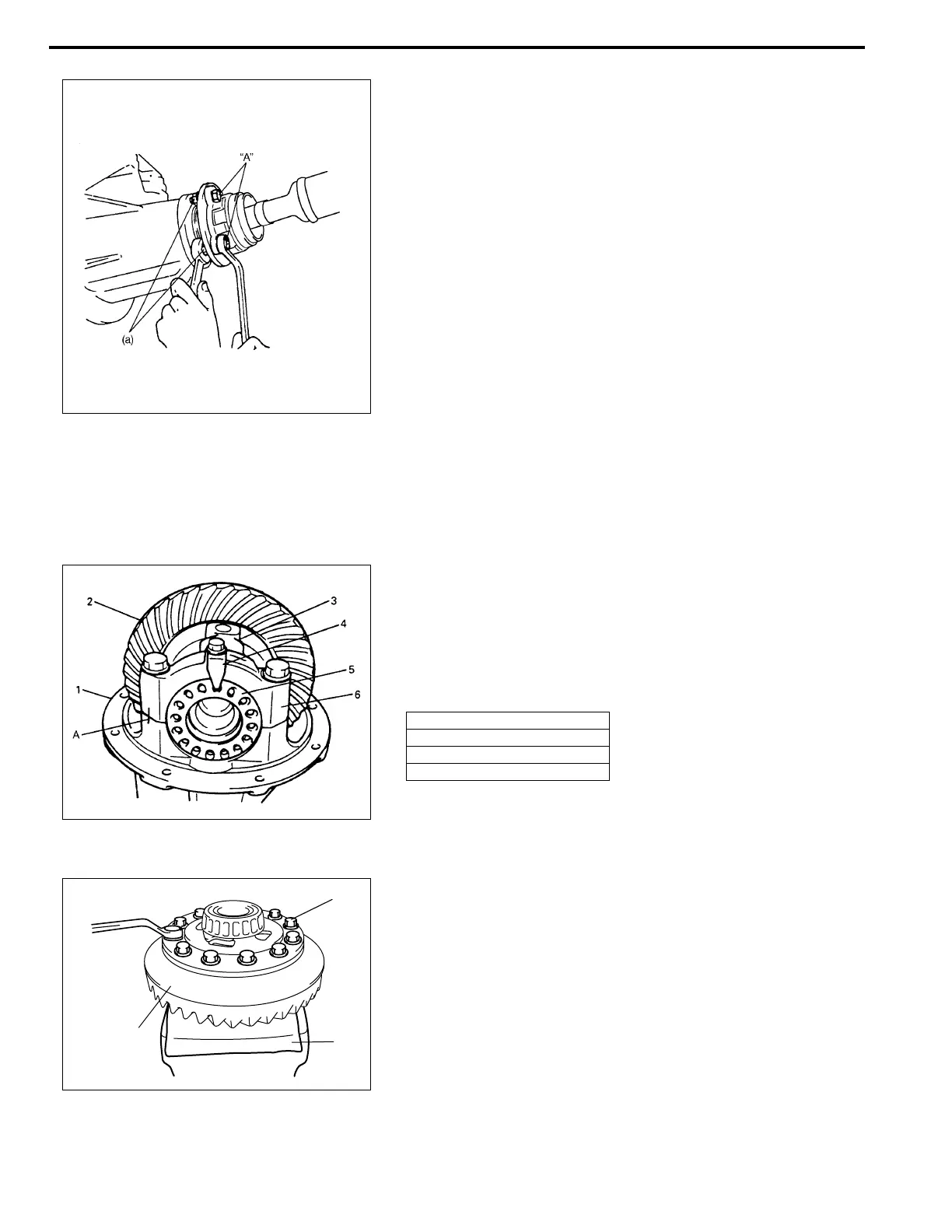
3) Install propeller shaft to joint flange aligning match marks
and torque flange nuts to specification. Apply thread lock
cement to thread part of bolt if reused.
“A” : Cement 99000-32110
Tightening torque
Propeller shaft flange nuts (a) :
60 N·m (6.0 kg-m, 43.5 lb-ft)
4) Install right and left rear axle shafts and drums.
(Refer to “REAR AXLE INSTALLATION” of Section 3E and
rear brake drum installation of Section 5.)
5) Install wheels.
6) Fill hypoid gear oil as specified and tighten plug to specifica-
tion.
7) Lower lift.
Unit Repair
Disassembling Unit
1) Hold differential assembly securely and put identification
marks on differential side bearing caps (6).
2) Take off differential side bearing lock plates (4) and differen-
tial side bearing caps (6) by removing their bolts and then
take out bearing adjusters (5), side bearing outer races and
drive bevel gear with differential case.
3) Remove drive bevel gear (hypoid gear), differential gears,
differential pinions and pinion shafts.
a) With aluminum plates (2) placed on vise first, grip differen-
tial case with it and remove drive bevel gear (hypoid gear)
(3) by removing its bolts (1).
1. Differential carrier
2. Drive bevel gear assembly
3. Differential case
A: Identification mark
1
3
2

 Loading...


