8E-10 CRUISE CONTROL SYSTEM
Cruise Main Switch, Coast/Set, Resume/Accel and Cancel Switches Circuits
Check
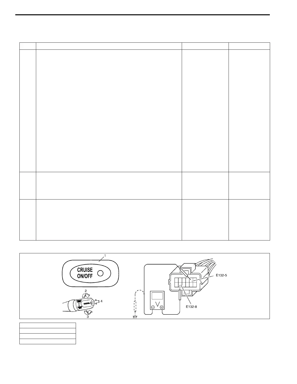
Fig. for Step 1
Step Action Yes No
1 Switch Circuit Check
1) Disconnect connector from cruise control module with
ignition switch OFF.
2) Check for proper connection to cruise control module at
terminal E132-8.
3) If OK, check resistance between terminal E132-8 and
E132-5 under each condition below.
Switch circuit specification (resistance)
All switches OFF : Infinity
COAST/SET switch rotated (ON) : 200 – 240 Ω
ΩΩ
Ω
RESUME/ACCEL switch rotated (ON) : 820 – 1000 Ω
ΩΩ
Ω
CANCEL switch pressed (ON) : About 0 Ω
ΩΩ
Ω
4) Turn ignition switch ON and check voltage between termi-
nal E132-8 and ground under each condition below.
Switch circuit specification (voltage)
Cruise main switch released (OFF) : 0 V
Cruise main switch pressed (ON) : 10 – 14 V
Are check results in above steps 3) and 4) satisfactory?
Switch circuit is
OK.
Go to Step 2.
2 Cruise Main Switch Check
1) Check cruise main switch for operation referring to “Cruise
Main Switch Inspection” in this section.
Is switch in good condition?
Go to step 3. Replace.
3 COAST/SET, RESUME/ACCEL and CANCEL Switches Check
1) Check COAST/SET, RESUME/ACCEL and CANCEL
switches for operation referring to “COAST/SET,
RESUME/ACCEL and CANCEL SWITCHES” in this sec-
tion.
Are all switches in good condition?
“BLK/YEL” or “LT
GRN” circuit is
open or short.
Replace.
1. Cruise main switch
2. “RESUME ACCEL” switch
3. “COAST SET” switch
4. “CANCEL” switch

 Loading...


