ENGINE GENERAL INFORMATION AND DIAGNOSIS (H27 ENGINE) 6-1-57
TROUBLESHOOTING
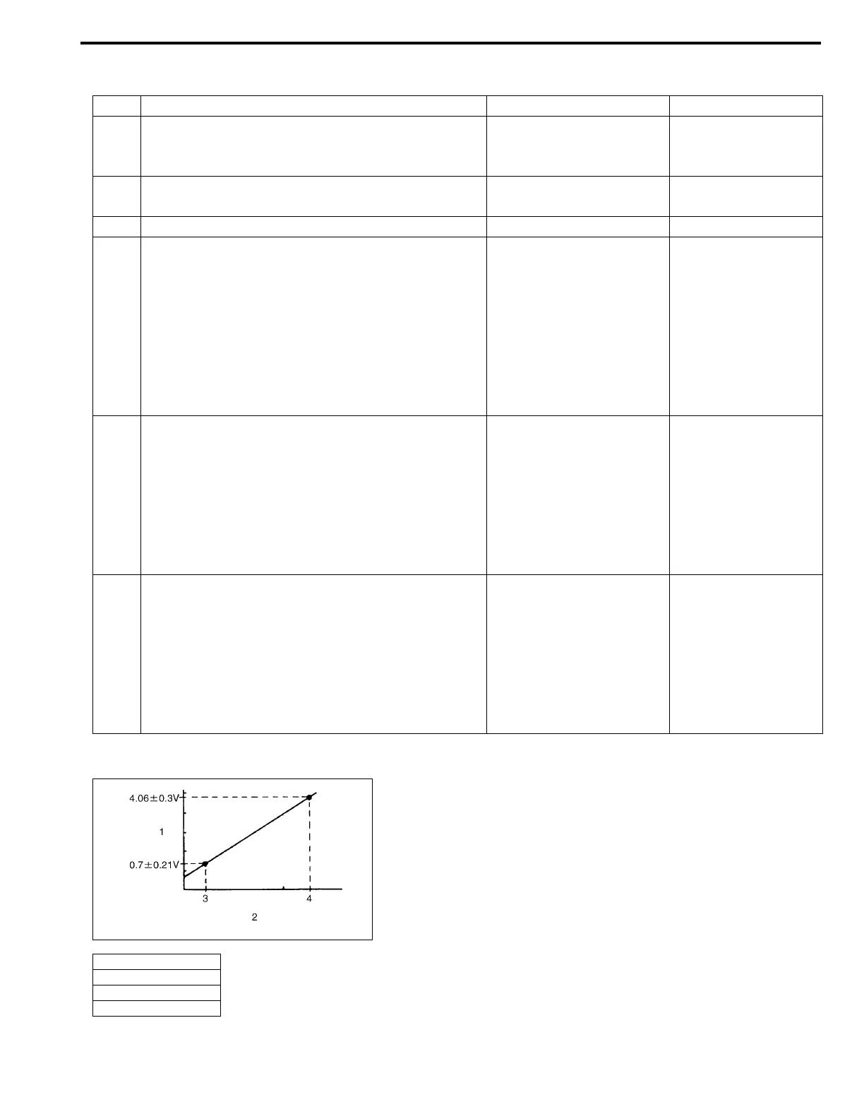
Fig. for Steps 4 and 5
Step Action Yes No
1 Was “ENGINE DIAG. FLOW TABLE” performed? Go to Step 2. Go to “ENGINE
DIAG. FLOW TABLE”
in this section.
2 Is there a DTC related to TP sensor (DTC P0120)? Go to applicable DTC
Diag. Flow Table.
Go to Step 3.
3 Do you have SUZUKI scan tool ? Go to Step 4. Go to Step 5.
4 Check TP sensor and its circuit (using SUZUKI
scan tool) :
1) Turn ignition switch OFF and connect SUZUKI
scan tool to DLC.
2) Turn ignition switch ON and check TP sensor
output voltage when throttle valve is at idle posi-
tion and fully opened.
Does voltage vary within specified value linearly as
shown in the figure?
Substitute a known-good
ECM (PCM) and recheck.
Go to Step 6.
5 Check TP sensor and its circuit (not using SUZUKI
scan tool) :
1) Turn ignition switch ON.
2) Check voltage at terminal C51-3-9 of ECM con-
nector connected, when throttle valve is at idle
position and fully opened.
Does voltage vary within specified value linearly as
shown in the figure?
If voltmeter was used,
check terminal C51-3-9 for
poor connection.
If OK, substitute a known-
good ECM (PCM) and
recheck.
Go to Step 6.
6 Check TP sensor :
1) Turn ignition switch OFF.
2) Disconnect TP sensor connector.
3) Check for proper connection to TP sensor at
each terminal.
4) If OK, check TP sensor for resistance referring
to “TP SENSOR” in Section 6E2.
Is check result satisfactory?
High resistance in “GRY/
RED”, “RED/GRN” or
“GRY/YEL” circuit.
If wire and connection are
OK, substitute a known-
good ECM (PCM) and
recheck.
Replace TP sensor.
1. Voltage
2. Throttle opening
3. At idle position
4. Fully open

 Loading...


