ENGINE GENERAL INFORMATION AND DIAGNOSIS (H27 ENGINE) 6-1-107
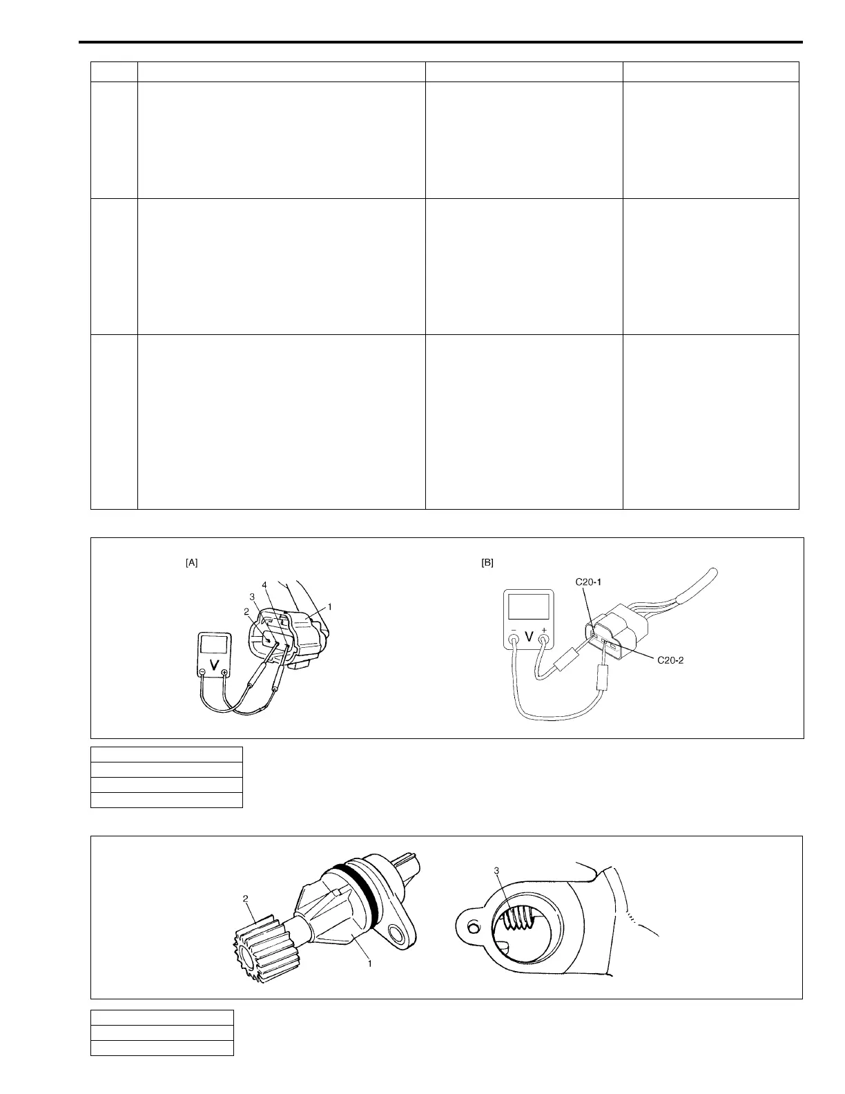
[A] Fig. for Step 3 / [B] Fig. for Step 4, 6, 7
Fig. for Step 5
5 VSS visual inspection:
1) Remove VSS referring to “TRANSFER”
section.
2) Check VSS drive and driven gears for
damage and excessive wear.
Are they in good condition?
Poor VSS connection or VSS
malfunction.
If connection is OK, substi-
tute a known-good VSS and
recheck.
Replace VSS.
6 Speedometer circuit check:
1) With ignition switch OFF, disconnect
G11 coupler from combination meter.
2) With ignition switch ON leaving engine
OFF, check voltage between C20-1 and
C20-2 terminal of VSS coupler.
Is voltage 4 V or more?
Substitute a known-good
combination meter and
recheck.
Go to Step 7.
7 Cruise control module circuit check (if
equipped):
1) With ignition switch OFF, disconnect
E132 coupler from cruise control mod-
ule.
2) With ignition switch ON leaving engine
OFF, check voltage between C20-1 and
C20-2 terminal of VSS coupler.
Is voltage 4 V or more?
Substitute a known-good
cruise control module and
recheck.
“BLU/YEL” wire open/
short or faulty ECM
(PCM).
If wire and connection are
OK, substitute a known-
good ECM (PCM) and
recheck.
1. VSS coupler
2. “BLU/YEL” (C20-1) terminal
3. “BLK/YEL” (C20-2) terminal
4. “BLU/BLK” (C20-3) terminal
Step Action Yes No
1. VSS coupler
2. VSS driven gear
3. VSS drive gear

 Loading...


