6-1-124 ENGINE GENERAL INFORMATION AND DIAGNOSIS (H27 ENGINE)
Table B-6 A/C Condenser Fan Motor Relay Control System Inspection (If
Equipped)
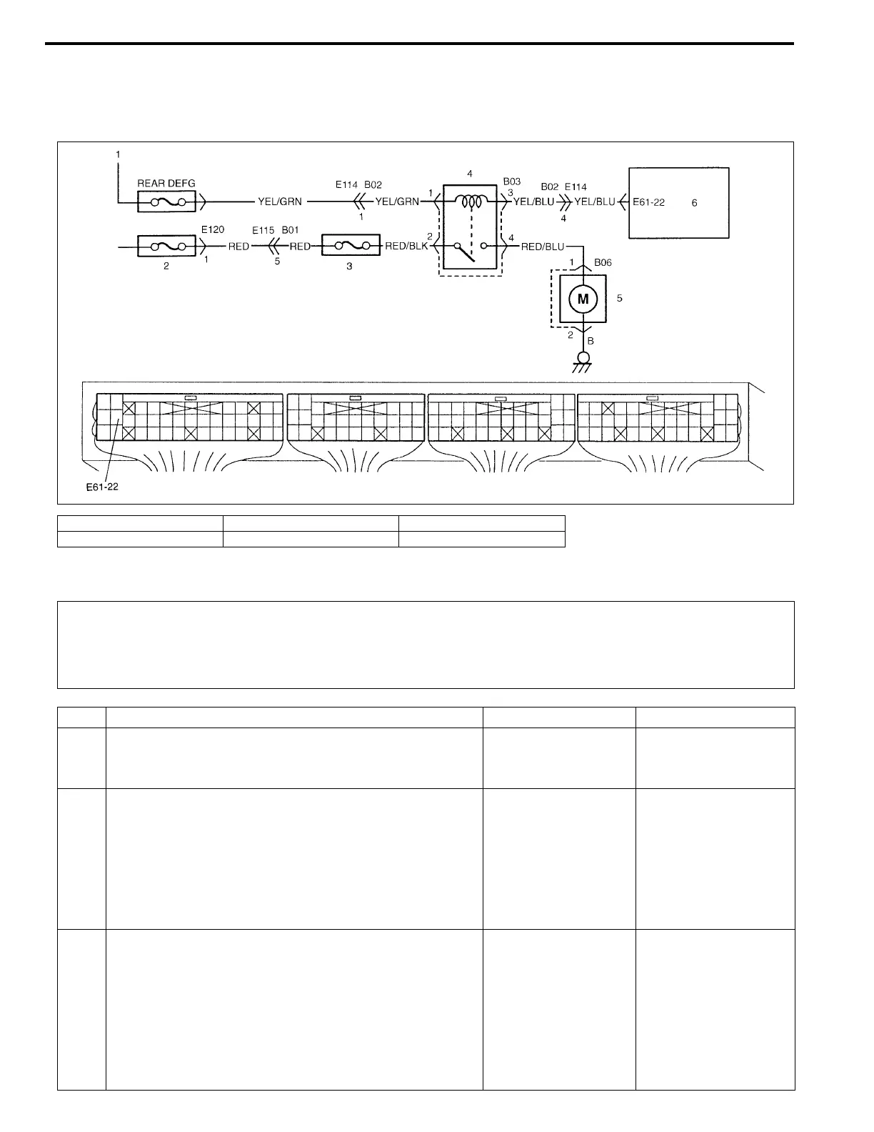
WIRING DIAGRAM
INSPECTION
1. To ignition switch 3. A/C fuse 5. A/C condenser fan motor
2. Main fuse 4. A/C condenser fan motor relay 6. ECM (PCM)
WARNING:
Keep hands, tools, and clothing away from A/C condenser fan to help prevent personal injury. This
fan is electric and can come on whether or not the engine is running. The fan can start automatically
in response to the ECT sensor with the ignition switch in the “ON” position.
Step Action Yes No
1 1) Check DTC referring to “DTC CHECK” in this sec-
tion.
Is there any malfunction DTC?
Go to applicable DTC
Diag. Flow Table.
Go to Step 2.
2 1) Check A/C condenser fan for operation.
A/C condenser fan should be operated under follow-
ing condition A or B only.
A : When engine is running and A/C is operating.
B : When engine coolant temp. is 113°C (235°F) or
more with ignition switch ON.
Is check result as specified?
This system is in
good condition.
Go to Step 3.
3 1) Remove ECM (PCM) cover.
2) Check voltage between E61-22 terminal of ECM
(PCM) connected coupler and ground.
Other than conditions A and B in Step 2 :
10 – 14 V
Under condition A or B in Step 2 :
0 – 1 V
Is check result as specified?
Fuse blown, “RED”,
“RED/BLK” or “RED/
BLU” circuit open,
malfunction of con-
denser fan motor or
relay.
“YEL/GRN” circuit
open, “YEL/BLU” cir-
cuit open or short, or
relay malfunction.
If above are OK, sub-
stitute a known-good
ECM (PCM) and
recheck.

 Loading...


