ENGINE MECHANICAL (H27 ENGINE) 6A2-27
12) Disconnect the following electric lead wires :
• Injector wire coupler
• CMP sensor coupler
• Ignition coil couplers
• CKP sensor coupler
• MAP sensor coupler
• TP sensor (1) coupler
• IAC valve (2) coupler
• Earth wire (3) from surge tank
• EVAP canister purge valve coupler
• EGR valve coupler
• Oxygen sensor -1 and -2 couplers referring to “Exhaust Man-
ifold” in this section
• Coolant temperature sensor coupler
• Knock sensor coupler
• Generator wires
• Starter wires
• Oil pressure wire
• P/S pump wire
• Earth wire from generator bracket
• Engine block heater (if equipped)
13) Remove clamps and brackets.
14) Disconnect the following hoses :
• Heater hose from heater water pipe
• Heater hose from water outlet cap
• EVAP canister hose from canister pipe
• Brake booster vacuum hose
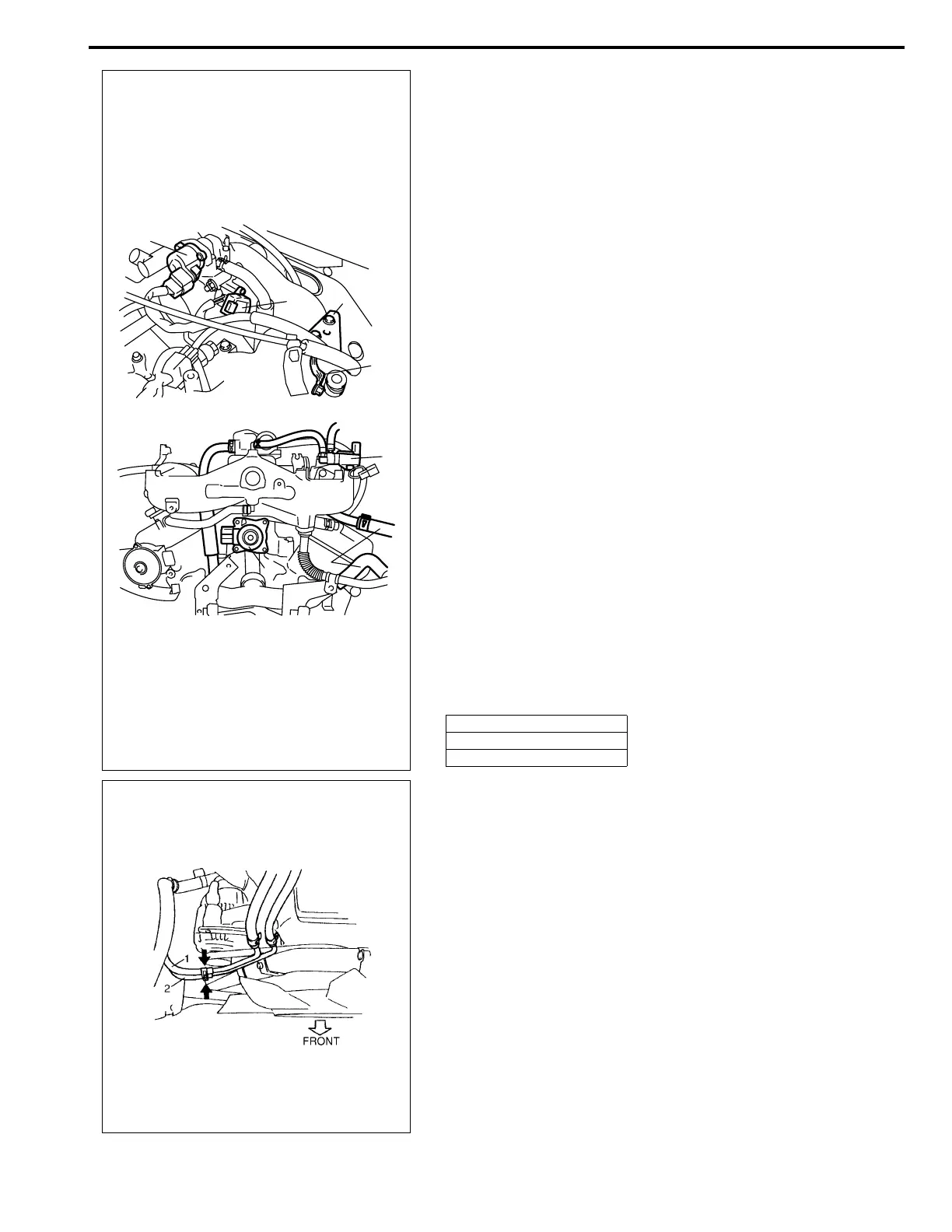
15) Remove EVAP canister purge valve (5).
16) Disconnect the following hoses at the location shown in the
figure :
• Fuel feed hose (1) from fuel feed pipe
• Fuel return hose from (2) fuel return pipe
17) Remove P/S pump assembly. Refer to “POWER STEERING
PUMP” in Section 3B1.
18) Remove A/C compressor assembly. Refer to “COMPRES-
SOR ASSEMBLY” in Section 1B.
19) Remove steering shaft lower assembly. Refer to “STEERING
LOWER SHAFT ASSEMBLY” in Section 3C1.
20) Raise vehicle.
21) Remove front differential housing with differential from chas-
sis if equipped. Refer to “DISMOUNTING” in Section 7E.
22) Remove exhaust No.1 pipe. Refer to “EXHAUST MANI-
FOLD” in this section.
23) Remove exhaust manifold stiffener from transmission.
4. Clamp bracket
6. EGR valve
7. Heater hose
2
1
4
3
7
5
6

 Loading...


