ENGINE MECHANICAL (H27 ENGINE) 6A2-31
Main bearing clearance
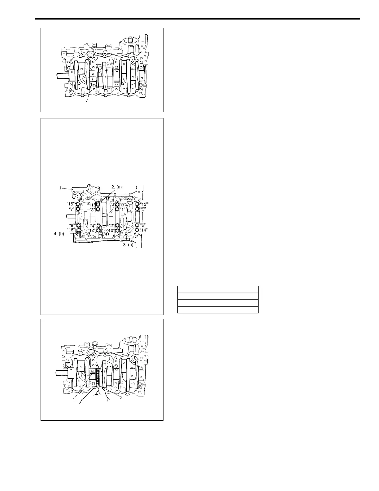
Check clearance by using gaging plastic (1) according to the fol-
lowing procedure.
1) Remove crankcase.
2) Clean bearings and main journals.
3) Place a piece of gaging plastic to full width of bearing (paral-
lel to crankshaft) on journal, avoiding oil hole.
4) Install crankcase to cylinder block.
Tighten crankcase bolts, following sequence in the figure.
Tighten crankcase bolts to specified torque.
Tightening torque
Thrust and journal bearing cap bolt (8 mm thread diame-
ter) (a) :
60 N·m (6.0 kg-m, 43.5 lb-ft)
Thrust and journal bearing cap bolt (10 mm thread diame-
ter) (b) :
27 N·m (2.7 kg-m, 19.5 lb-ft)
5) Remove crankcase and using scale (2) on gaging plastic (1)
envelop, measure gaging plastic (1) width at its widest point.
If clearance exceeds its limit, replace bearing. Always
replace both upper and lower inserts as a unit.
A new standard bearing may produce proper clearance. If
not, it will be necessary to regrind crankshaft journal for use
of 0.25 mm undersize bearing.
After selecting new bearing, recheck clearance.
Main Bearing Clearance
Standard : 0.024 – 0.044 mm (0.0009 – 0.0017 in.)
Limit : 0.060 mm (0.0023 in.)
NOTE:
Tighten 10 mm thread diameter bolts first (following the
order shown in the figure) then tighten 8 mm thread
diameter bolts.
NOTE:
Do not rotate crankshaft while gaging plastic is installed.
1. Lower crankcase
2. Bolt (10 mm thread diameter)
3. Bolt (8 mm thread diameter)
4. Long bolt (8 mm thread diameter)

 Loading...


