10B-16 AIR BAG SYSTEM
Table A - “AIR BAG” Warning Lamp Comes ON Steady
Table B - “AIR BAG” Warning Lamp Does Not Come ON
Table C - “AIR BAG” Warning Lamp Flashes
Table D - “AIR BAG” Warning Lamp Cannot Indicate Flashing Pattern of DTC
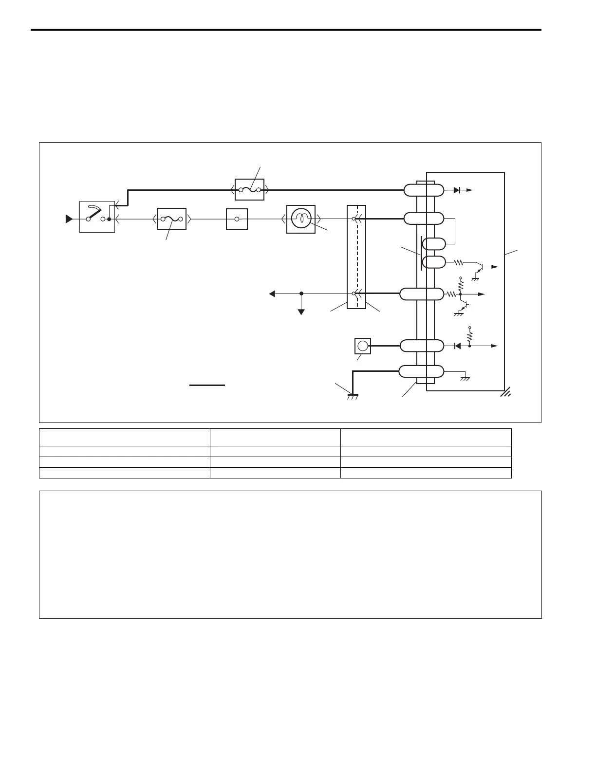
WIRING DIAGRAM
1. From main fuse 5. “AIR BAG” fuse 9. To ECM, TCM (if equipped) and ABS control
module (if equipped)
2. Ignition switch 6. Connection detection pin 10. “AIR BAG” monitor coupler
3. “IG METER” fuse 7. SDM 11. Ground for air bag system
4. “AIR BAG” warning lamp in combination meter 8. To DLC [A]: Air bag harness
1
2
3
4
BLK/BLU
BLU/BLK BLU/RED
BLK/WHT BLK/WHT
BLU
BLU
6
PPL/RED
PPL/RED
8
9
10
11
PPL
BLK
“Q04”
“Q01”
Q01-2
Q01-20
Q01-15
Q01-17
L1
L2
SDL
DNS
GND
LA
Q01-4
IG
7
[A]
12V
5V
“G27”
“Q02”
5
CAUTION:
• Be sure to perform AIR BAG DIAGNOSTIC SYSTEM CHECK before starting diagnosis according to
flow table.
• When measurement of resistance or voltage is required in this table, use a tester along with a cor-
rect terminal adapter from special tool (Connector test adapter kit).
• When a check for proper connection is required, refer to INTERMITTENT AND POOR CONNEC-
TIONS in this section.
• If there is open circuit in the air bag wire harness, connector or terminal is found damaged, replace
the wire harness, connector and terminal as an assembly.

 Loading...


