AIR BAG SYSTEM 10B-21
Table E - SDM Cannot Communicate through The Serial Data Circuit
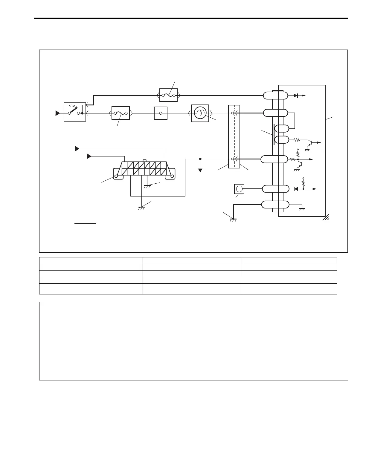
WIRING DIAGRAM
TABLE TEST DESCRIPTION
STEP 1 : An improper connection to the data link connector (DLC) will prevent communications from being
established.
STEP 2 : This test checks whether it is possible to communicate with other control module.
STEP 3 : This test checks for an open in “PPL/RED” circuit (in air bag harness).
[A]: Air bag harness 5. “AIR BAG” fuse 10. “AIR BAG” monitor coupler
1. From main fuse 6. Connection detection pin 11. Ground for air bag system
2. Ignition switch 7. SDM 12. Ground on body
3. “IG METER” fuse 8. DLC 13. Ground on Engine block
4. “AIR BAG” warning lamp in combination lamp 9. To ECM, TCM (if equipped) and ABS con-
trol module (if equipped)
14. Immobilizer control module (if equipped)
14
1
PPL/WHT
BLK
BLK/YEL
WHT
10
11
PPL
BLK
“Q04”
Q01-15
Q01-17
DNS
GND
7
[A]
5V
8
12
13
1
2
3
4
BLK/BLU
BLU/BLK BLU/RED
BLK/WHT BLK/WHT
BLU
BLU
6
PPL/RED
PPL/RED
9
Q01-2
Q01-20
L1
L2
SDL
LA
Q01-4
IG
12V
“G27”
“Q02”
5
CAUTION:
• Be sure to perform AIR BAG DIAGNOSTIC SYSTEM CHECK before starting diagnosis according to
flow table.
• When measurement of resistance or voltage is required in this table, use a tester along with a cor-
rect terminal adapter from special tool (Connector test adapter kit).
• When a check for proper connection is required, refer to INTERMITTENT AND POOR CONNEC-
TIONS in this section.
• If there is open circuit in the air bag wire harness, connector or terminal is found damaged, replace
the wire harness, connector and terminal as an assembly.

 Loading...


