10B-32 AIR BAG SYSTEM
DTC B1025 :
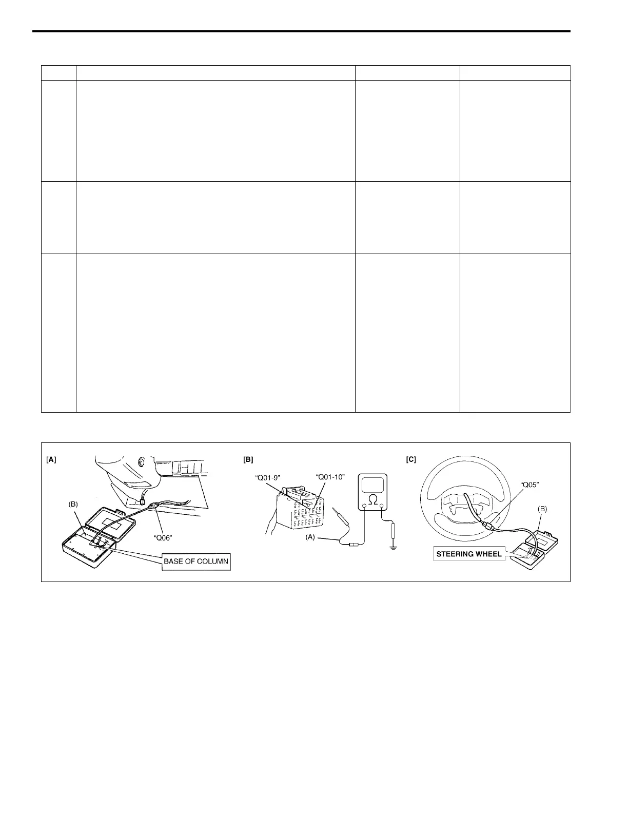
[A] Fig. for STEP 1 and 2/[B] Fig. for STEP 2/[C] Fig. for STEP 3
Special tool
(A) : 09932-75020
(B) : 09932-75010
Step Action Yes No
1 1) With ignition switch OFF, disconnect contact coil con-
nector located near the base of the steering column.
2) Check proper connection to contact coil at terminals
in “Q06” connector.
3) If OK then connect Special Tool (B) to contact coil
connector disconnected at step 1).
With ignition switch ON, is DTC B1025 current?
Go to step 2. Go to step 3.
2 1) With ignition switch OFF, disconnect Special Tool (B)
and SDM connector.
2) Measure voltage from “Q01-9” terminal to body
ground and from “Q01-10” terminal to body ground.
With ignition switch ON, are they 1 V or less?
Substitute a known-
good SDM and
recheck.
Repair short from
“GRN” or “GRN/RED”
wire circuit to power
circuit.
3 1) With ignition switch OFF, disconnect Special Tool (B)
then reconnect contact coil connector located near
the base of the steering column.
2) Remove driver air bag (inflator) module from steering
wheel (Refer to DRIVER AIR BAG (INFLATOR)
MODULE in Section 3C1).
3) Check proper connection to driver air bag (inflator)
module at terminals in “Q05” connector.
4) If OK then connect Special Tool (B) to “Q05” connec-
tor.
With ignition switch ON, is DTC B1025 current?
Ignition switch OFF.
Replace contact coil
assembly (Refer to
COMBINATION
SWITCH/CON-
TACT COIL AND
COMBINATION
SWITCH ASSEM-
BLY in Section
3C1).
Ignition switch OFF.
Replace driver air
bag (inflator) module
(Refer to DRIVER
AIR BAG (INFLA-
TOR) MODULE in
Section 3C1).
NOTE:
Upon completion of inspection and repair work, perform following items.
• Reconnect all air bag system components, ensure all components are properly mounted.
• Clear diagnostic trouble codes (Refer to DTC CLEARANCE), if any.
• Repeat AIR BAG DIAGNOSTIC SYSTEM CHECK to confirm that the trouble has been corrected.

 Loading...


