10B-34 AIR BAG SYSTEM
DIAGNOSTIC FLOW TABLE
DTC B1031 :
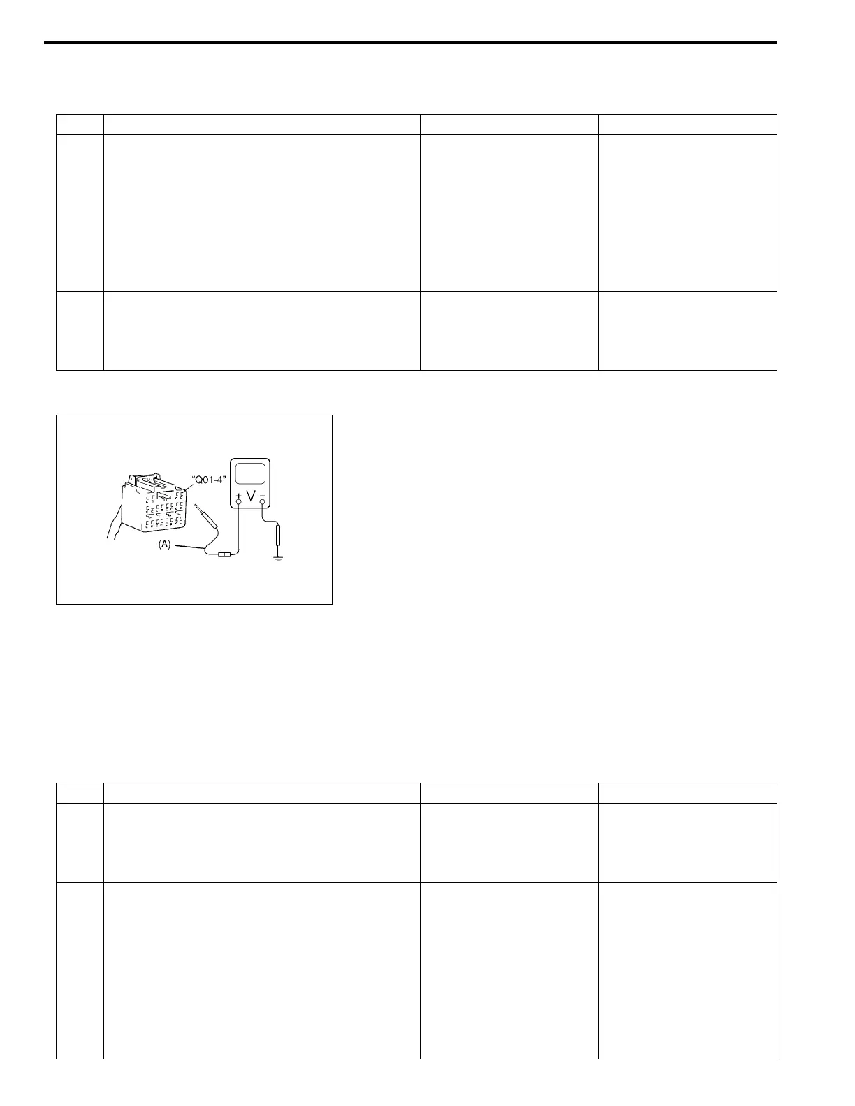
Fig. for STEP 1
Special tool
(A) : 09932-75020
DTC B1032 :
Step Action Yes No
1 1) With ignition switch OFF, disconnect SDM
connector.
2) Check proper connection to SDM at “Q01-4”
terminal.
3) If OK then ignition switch ON, and then
check voltage from “Q01-4” terminal on
SDM connector to body ground.
Is voltage 14 V or less?
Go to step 2. Check Charging System
and repair as necessary.
(Refer to DIAGNOSIS in
Section 6H)
2 1) With ignition switch OFF, reconnect SDM
connector.
With ignition switch ON, is DTC B1031 current?
Substitute a known-good
SDM and recheck.
Check Charging System
and repair as necessary.
(Refer to DIAGNOSIS in
Section 6H)
NOTE:
Upon completion of inspection and repair work, perform following items.
• Reconnect all air bag system components, ensure all components are properly mounted.
• Clear diagnostic trouble codes (Refer to DTC CLEARANCE), if any.
• Repeat AIR BAG DIAGNOSTIC SYSTEM CHECK to confirm that the trouble has been corrected.
Step Action Yes No
1 1) Measure voltage on battery.
Is voltage 11 V or more?
Go to step 2. Check Charging System
and repair as necessary.
(Refer to DIAGNOSIS in
Section 6H)
2 1) With ignition switch OFF, disconnect SDM
connector.
2) Check proper connection to SDM at “Q01-4”
terminal.
3) If OK then ignition switch ON, and then
check voltage from “Q01-4” terminal on
SDM connector to body ground.
Is voltage 8 V or more?
Go to step 3. Possibly faulty points are
as follows. Check each of
them and repair as neces-
sary.
• Circuit from battery to
“Q01” connector
• Charging System
(Refer to DIAGNOSIS
in Section 6H)

 Loading...


