9A-4 Wiring Systems:
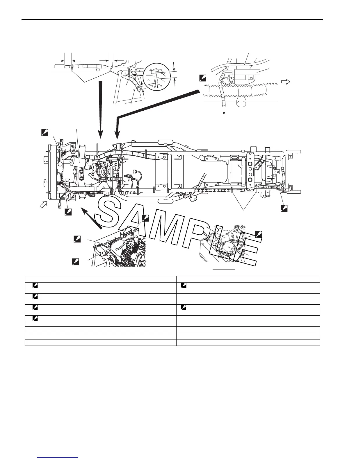
Wiring Harness Routing Diagram (LT-A750XP/ZK9)
B931G39102004
“b”
2
3
3
“B”
2
1
4
7
6
5
VIEW A
“A”
1
“a”
“b”
1
1
“c”
“D”
8
9
“C”
7
FWD
I931G3910905-02
1. Clamp 9. Throttle cable
2. Clamp
: Bind the wiring harness and hose with the clamp.
“B”: Pass the wiring harness and cooling fan lead wire over the radiator
hose.
3. Clamp
: Bind the wiring harness and cooling fan thermo switch with the clamp.
“C”: To power source.
4. Clamp
: Bind the wiring harness and back up relay (For P-17) with the clamp.
“D”: Pass the wiring harness under of the throttle cable.
5. Clamp
: Bind the EPS motor lead wire and EPS control unit lead wires.
“a”: 60 – 80 mm (2.4 – 3.2 in)
6. EPS control unit “b”: 20 – 30 mm (0.8 – 1.2 in)
7. EPS motor “c”: 10 – 15 mm (0.4 – 0.6 in)
8. Ignition coil
 Loading...


