6C-7 Power Assisted Steering System:
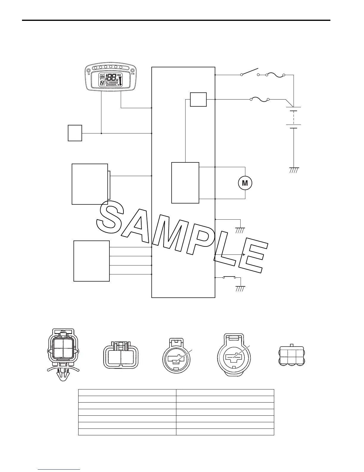
EPS Control Unit Diagram (LT-A750XP/ZK9)
B931G36302002
Refer to “Wire Color Symbols in Section 0A in related manual”.
EPS control unit coupler (EPS control unit harness end)
30 A
40 A
Ignition
switch
EPS
MAIN
Fail-safe
relay
EPS
motor
Speed sensor
(Vehicle speed)
Speedometer
ECM
TACHO
Motor drive circuit
EPS countrol unit
SDS
Mode selsct switch
Torque sensor
4
5
1
31
6
3
7
9
10
8
2
12
11
14
13
Y
W
Bl/B
R
G
W
B
O/Y
R/B
B
R
B/W
Gr/R
W/R
I931G3630071-01
10 9
8
7
123
456
1112
1314
I931H1630092-01
1. Engine speed signal 8. Power source
2. Ignition signal for EPS control unit 9. Motor output (–)
3. Mode select switch 10. Motor output (+)
4. “EPS” warning light 11. Torque sensor signal (Main)
5. Vehicle speed signal 12. Power supply for torque sensor
6. SDS 13. Ground for torque sensor
7. Ground for EPS control unit 14. Torque sensor signal (Sub)
 Loading...


