0B-2 Maintenance and Lubrication:
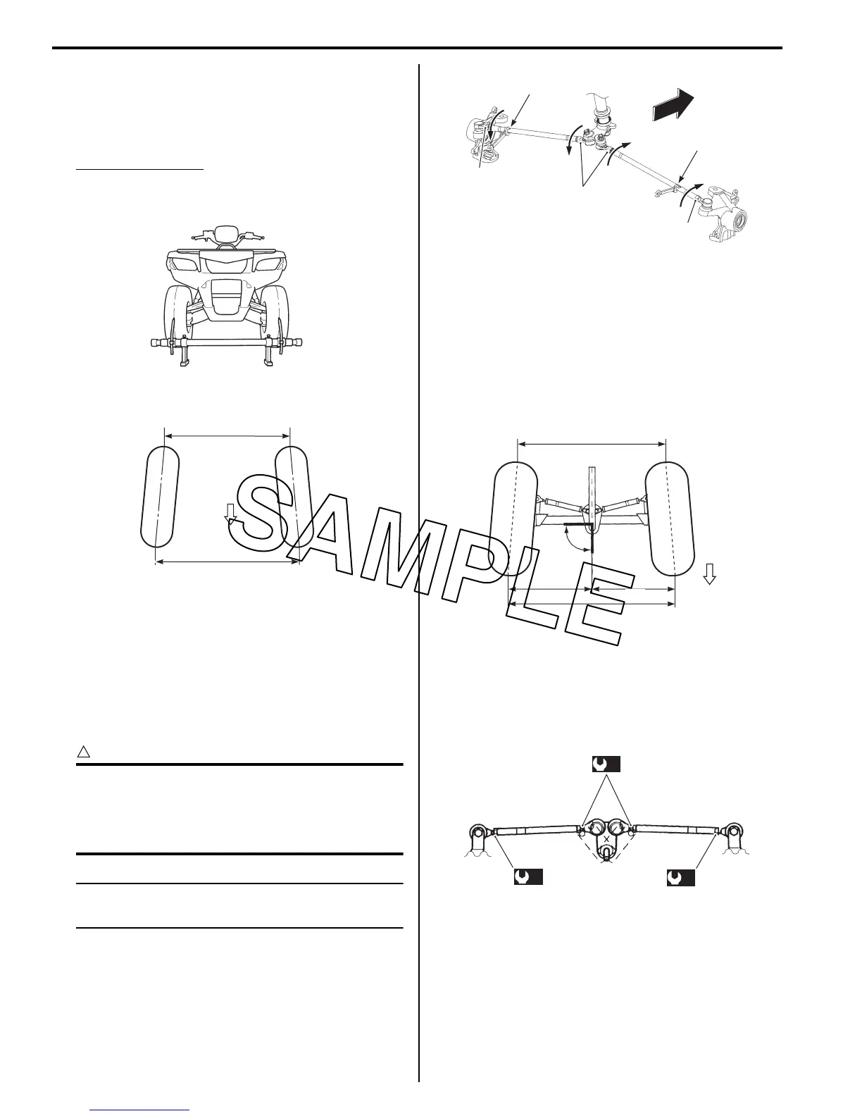
5) Measure the distances (“A” and “B”) between the
front wheels. Subtract the measurement of “A” from
that of “B” to find the toe-out. If the toe-out is not
within specification, adjust the tie-rod to the right or
left until the toe-out is within the specified range.
Toe-out (“B” – “A”)
Standard: 5 ± 4 mm (0.20 ± 0.16 in)
If the toe-out is out of specification, bring it into the
specified range. Refer to “Toe Adjustment (LT-A750XP/
ZK9) (Page 0B-2)”.
Toe Adjustment (LT-A750XP/ZK9)
B931G30206031
Adjust the toe-out as follows:
1) Loosen the lock-nuts (1), (2) on each tie-rod.
CAUTION
!
• The lock-nuts (2) have left-hand threads.
• When loosening and tightening the lock-
nuts, hold the tie-rod end with a open end
wrench.
NOTE
Hold the concave part “a” of tie-rod with a
wrench.
2) Temporarily tighten the four lock-nuts.
3) Check that the distances “C” and “D” are equal, as
shown. If the distances are not equal, adjust the tie-
rod to the right or left until the toe-out is within
specification. Check the toe-out again by measuring
distances “A” and “B”.
4) If the toe-out is not within specification, repeat the
adjustment as above until the proper toe-out is
obtained and distances “C” and “D” become equal.
5) After adjustment has been made, tighten the four
lock-nuts to the specified torque.
Tightening torque
Tie-rod lock-nut (a): 29 N·m (2.9 kgf-m, 21.0 lbf-
ft)
I931H1020057-01
FWD
“A”
“B”
I831G1020059-04
2
1
1
“a”
“a”
FWD
I931H1020079-02
“C”
Right angle
(90
°
)
FWD
“A”
“B”
“D”
I831G1020088-04
(a)
(a)
(a)
I831G1020089-01
 Loading...


