Charging System: 1J-2
• Tighten the crankshaft spacer nut (2) to the specified
torque with the special tool.
Special tool
(A): 09930–44530 (Rotor holder)
Tightening torque
Left crankshaft spacer nut (a): 38 N·m (3.8 kgf-m,
27.5 lbf-ft)
Battery Removal and Installation (LT-A750XP/
ZK9)
B931G31A06011
Removal
1) Remove the seat. Refer to “Seat Removal and
Installation in Section 9D in related manual”.
2) Remove the battery stay (1).
3) Disconnect the battery (–) lead wire (2).
4) Disconnect the battery (+) lead wire (3).
NOTE
Be sure to disconnect the battery (–) lead
wire (2) first, then disconnect the battery (+)
lead wire (3).
5) Remove the battery (4).
Installation
Install the battery in the reverse order of removal.
Pay attention to following point:
CAUTION
!
Never use anything except the specified
battery.
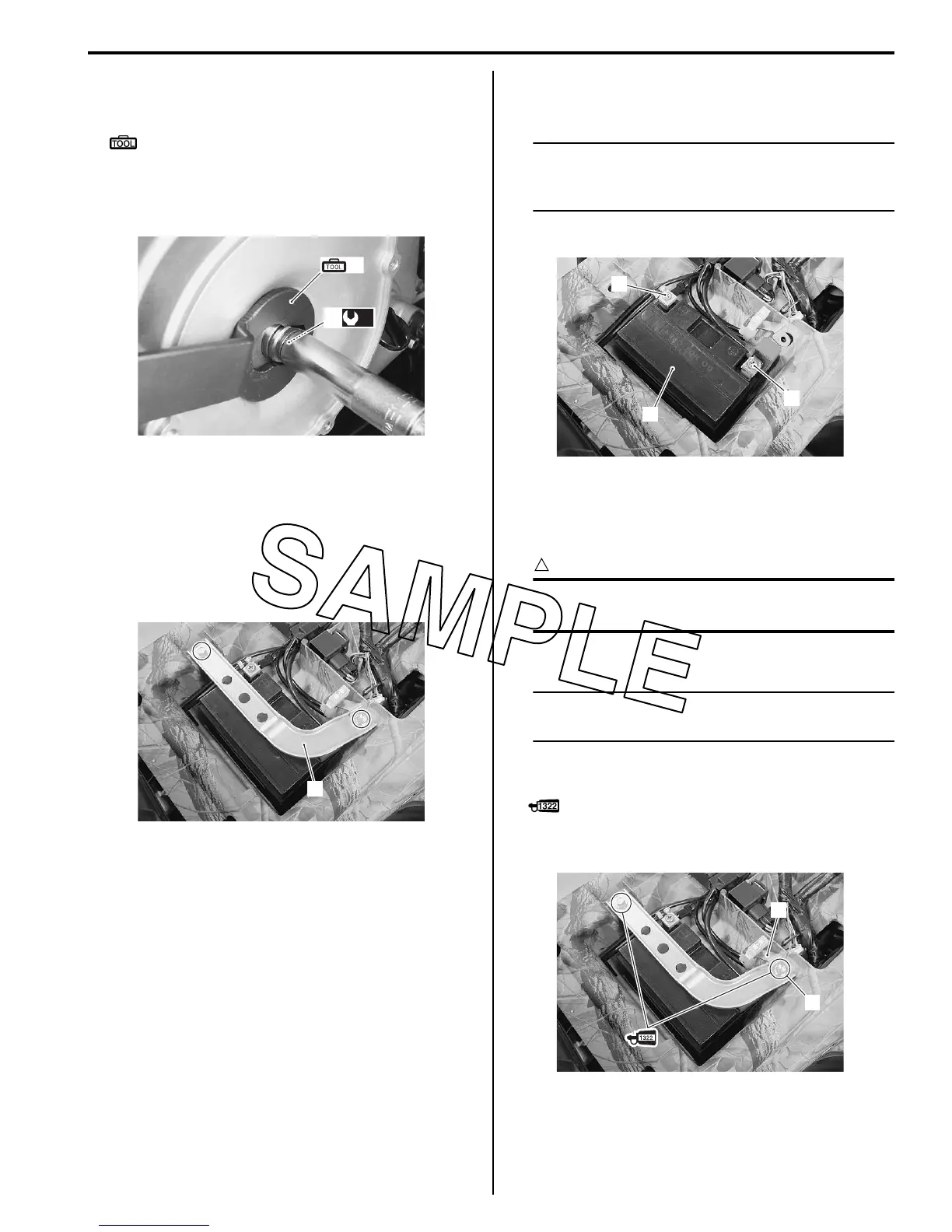
• Tighten the battery mounting bolts securely.
NOTE
Fit the EPS fuse bracket (2) to the mounting
bolt (1).
• Apply thread lock to the battery stay mounting bolts
and tighten them securely.
: Thread lock cement 99000–32110
(THREAD LOCK CEMENT SUPER “1322” or
equivalent)
(A)
(a)
2
I931G31A0004-01
1
I931G31A0005-01
2
4
3
I931G31A0006-01
1
2
I931G31A0007-02
 Loading...


