3A-2 Drive Chain / Drive Train / Drive Shaft:
Front Drive Shaft Disassembly and Assembly
(LT-A750XP/ZK9)
B931G33106011
Refer to “Front Drive Shaft Assembly Removal and
Installation in related manual”.
Disassembly
CAUTION
!
Do not disassemble the wheel side joint. If
any damages are found, replace it with a new
one.
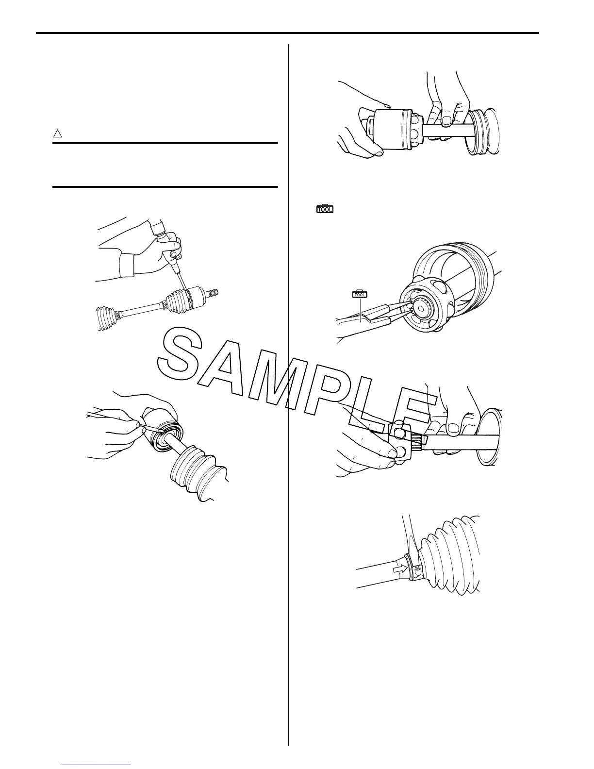
1) Remove the boot band of the differential side joint.
2) Slide the boot toward the center of the front drive
shaft and remove the stopper ring from the outer
race.
3) Remove the outer race from the front drive shaft.
4) Wipe off any grease and remove the snap ring.
Special tool
(A): 09900–06107 (Snap ring remover (Open
type))
5) Remove the cage from the front drive shaft.
6) Remove the boot band of the small diameter side.
I931H1310003-03
I831G1310006-01
I831G1310007-01
(A)
I831G1310022-01
I831G1310009-01
I931H1310004-02
 Loading...


