Calibration—434
HO RIZONTAL SYSTEM C ALIBRATION
Equipment Required
1. Test Oscilloscope
4. 42-Inch 50 £2 BNC Cable
2. Time-Mark Generator
5. 3-Inch Screwdriver
3. Standard Amplitude Calibrator
6. Low-Capacitance Screwdriver
Control Settings
Preset instrument controls to the settings given under
Preliminary Control Settings except as follows:
Sweep MODE AUTO
INTENSITY Visible Display
34. Adjust Sweep Generator Offset Adjustment
a. Connect a IX probe to the test oscilloscope vertical
input.
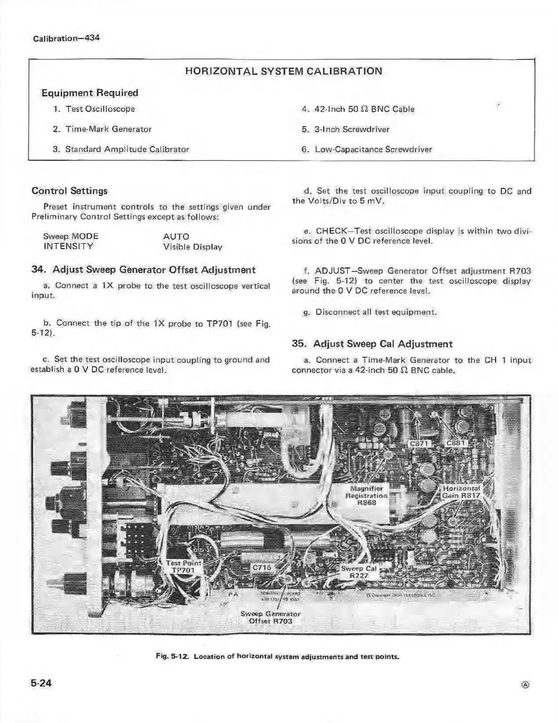
b. Connect the tip of the IX probe to TP701 (see Fig.
5-12).
c. Set the test oscilloscope input coupling to ground and
establish a 0 V DC reference level.
d. Set the test oscilloscope input coupling to DC and
the Volts/D iv to 5 mV.
e. CHECK—Test oscilloscope display is w ithin two divi
sions of the 0 V DC reference level.
f. ADJUST—Sweep Generator Offset adjustment R703
(see Fig. 5-12) to center the test oscilloscope display
around the 0 V DC reference level.
g. Disconnect all test equipment.
35. Adjust Sweep Cal Adjustment
a. Connect a Time-Mark Generator to the CH 1 input
connector via a 42-inch 50 £2 BNC cable.
M agnifier
Registration
R863 H
W k H orizontal
R817
Test P oint
TP701
ac-iSRzr
# ■ isr?0'' T fik r iU 9 : -
.
Sweep G enerator
O ffse t R703
5-24
Fig. 5-12. Location o f ho rizontal system adjustments and test po ints.
 Loading...


