Operating Instructions—434
10. Adjust the horizontal POSITION control so the
Channel 1 (reference) waveform crosses the center ho ri
zontal line at a vertical graticule line.
434. This method of phase difference measurement can be
used up to the frequency lim it of the vertical system. To
make the comparison, use the follow ing procedure.
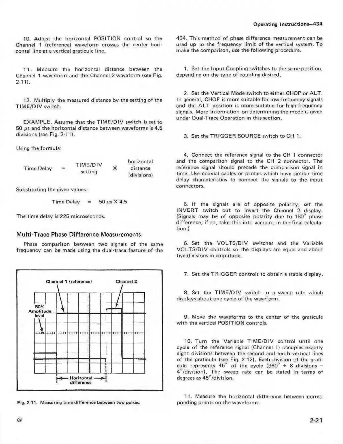
11. Measure the horizontal distance between the
Channel 1 waveform and the Channel 2 waveform (see Fig.
2-11).
12. M ultiply the measured distance by the setting of the
T IM E /D IV switch.
EXAM PLE, Assume that the T IM E /D IV switch is set to
50 /us and the horizontal distance between waveforms is 4.5
divisions (see Fig. 2-11).
1. Set the Inpu t Coupling switches to the same position,
depending on the type of coupling desired.
2. Set the Vertical Mode switch to either CHOP or A LT .
In general, CHOP is more suitable for low-frequency signals
and the A L T position is more suitable fo r high-frequency
signals. More inform ation on determ ining the mode is given
under Dual-Trace Operation in this section.
3. Set the TRIG G ER SOURCE switch to CH 1.
Using the form ula:
Time Delay
T IM E /D IV
setting
horizontal
distance
(divisions)
Substituting the given values:
4. Connect the reference signal to the CH 1 connector
and the comparison signal to the CH 2 connector. The
reference signal should precede the comparison signal in
time. Use coaxial cables or probes w hich have similar time
delay characteristics to connect the signals to the input
connectors.
Time Delay = 50 /is X 4.5
The time delay is 225 microseconds.
Multi-Trace Phase Difference Measurements
Phase comparison between tw o signals of the same
frequency can be made using the dual-trace feature of the
5. If the signals are of opposite polarity, set the
IN VE R T switch out to invert the Channel 2 display.
(Signals may be of opposite polarity due to 180° phase
difference; if so, take this into account in the final calcula
tion.)
6. Set the V O LT S /D IV switches and the Variable
V O L T S /D IV controls so the displays are equal and about
five divisions in am plitude.
Channel 1 (reference) Channel 2
\
7
50%
\
t
A m p litu d e
_
level
\
A
H o rizo ntal —
diffe re n ce
Fig. 2-11. M easuring tim e d ifference between tw o pulses.
7. Set the TRIGG ER controls to obtain a stable display.
8. Set the T IM E /D IV switch to a sweep rate which
displays about one cycle o f the waveform.
9. Move the waveforms to the center of the graticule
w ith the vertical POSITION controls.
10. Turn the Variable T IM E /D IV control u ntil one
cycle o f the reference signal (Channel 1) occupies exactly
eight divisions between the second and tenth vertical lines
of the graticule (see Fig. 2-12). Each division of the grati
cule represents 45° of the cycle (360° -5- 8 divisions =
4"/d ivisio n). The sweep rate can be stated in terms of
degrees as 45°/division.
11. Measure the horizontal difference between corres
ponding points on the waveforms.
2-21
 Loading...


