Operating Instructions—434
9. Measure the distance in divisions between the refer
ence line and the po int on the waveform at which the DC
level is to be measured. For example, in Fig. 2-8 the
measurement is made between the reference line and poin t
A.
10. Establish the polarity o f the signal. If the waveform
is above the reference line the voltage is positive; below the
line, negative (w ith the INV E R T switch in fo r Channel 2).
11. M u ltip ly the distance measured in step 9 by the
V O LT S /D IV switch setting. Include the attenuation factor
of the probe, if using a probe that does not have a scale
factor sw itching connector.
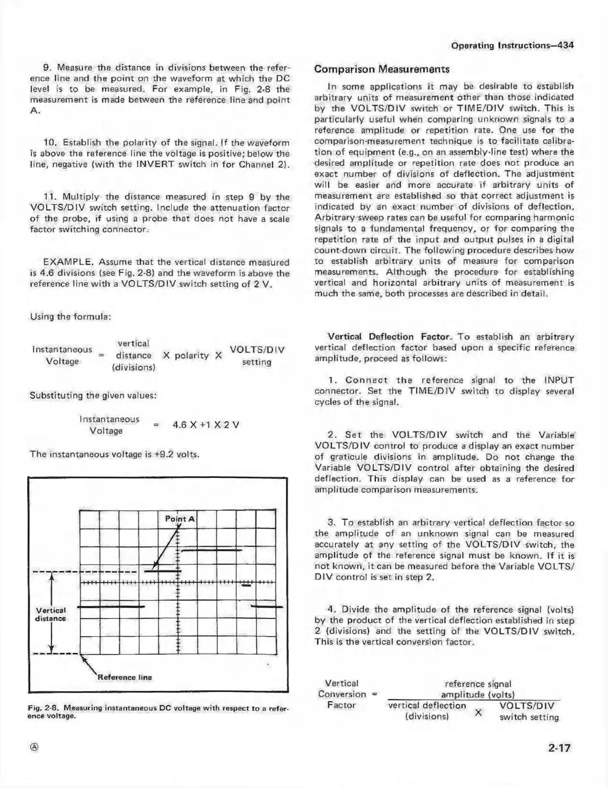
EXAM PLE. Assume that the vertical distance measured
is 4.6 divisions (see Fig. 2-8) and the waveform is above the
reference line w ith a V O LT S /D IV switch setting of 2 V.
Comparison Measurements
In some applications it may be desirable to establish
arbitrary units of measurement other than those indicated
by the V O L T S /D IV switch or T IM E /D IV switch. This is
particularly useful when comparing unknow n signals to a
reference amplitude or repetition rate. One use fo r the
comparison-measurement technique is to facilitate calibra
tion o f equipm ent (e.g., on an assembly-line test) where the
desired amplitude or repetition rate does not produce an
exact number of divisions of deflection. The adjustment
w ill be easier and more accurate if arbitrary units of
measurement are established so th at correct adjustment is
indicated by an exact number of divisions o f deflection.
A rb itra ry sweep rates can be useful fo r comparing harm onic
signals to a fundamental frequency, or fo r comparing the
repetition rate o f the input and outp ut pulses in a digital
count down circuit. The fo llow ing procedure describes how
to establish arbitrary units of measure fo r comparison
measurements. A lthough the procedure fo r establishing
vertical and horizontal arbitrary units of measurement is
much the same, both processes are described in detail.
Using the form ula:
instantaneous
Voltage
vertical
distance X polarity X
(divisions)
V O L T S /D IV
setting
Substituting the given values:
Instantaneous
Voltage
4.6 X +1 X 2 V
The instantaneous voltage is +9.2 volts.
Fig. 2-8. Measuring instantaneou s DC voltage w ith respect to a re fer
ence voltage.
Vertical D eflection Factor. T o establish an arbitrary
vertical deflection factor based upon a specific reference
am plitude, proceed as follow s:
1. C o n n e c t th e reference signal to the INPUT
connector. Set the T IM E /D IV switch to display several
cycles o f the signal.
2. Set the V O LT S /D IV switch and the Variable
V O LT S /D IV control to produce a display an exact number
of graticule divisions in am plitude. Do not change the
Variable V O LT S /D IV control after obtaining the desired
deflection. This display can be used as a reference fo r
am plitude comparison measurements.
3. To establish an arbitrary vertical deflection factor so
the am plitude of an unknown signal can be measured
accurately at any setting of the VO LT S /D IV switch, the
am plitude of the reference signal m ust be know n. If it is
not know n, it can be measured before the Variable V O LTS /
D IV control is set in step 2.
4. Divide the amplitude of the reference signal (volts)
by the product of the vertical deflection established in step
2 (divisions) and the setting of the V O LT S /D IV switch.
This is the vertical conversion factor.
Vertical reference signal
Conversion =
____________
am plitude (volts)
_________
Factor vertical deflection V O LT S /D IV
(divisions) * switch setting
2-17
 Loading...


