Rackmounting—434
Fig. 6-2 . H a rd w are needed to m o u n t th e in s tru m e n t in the c a b ine t rack.
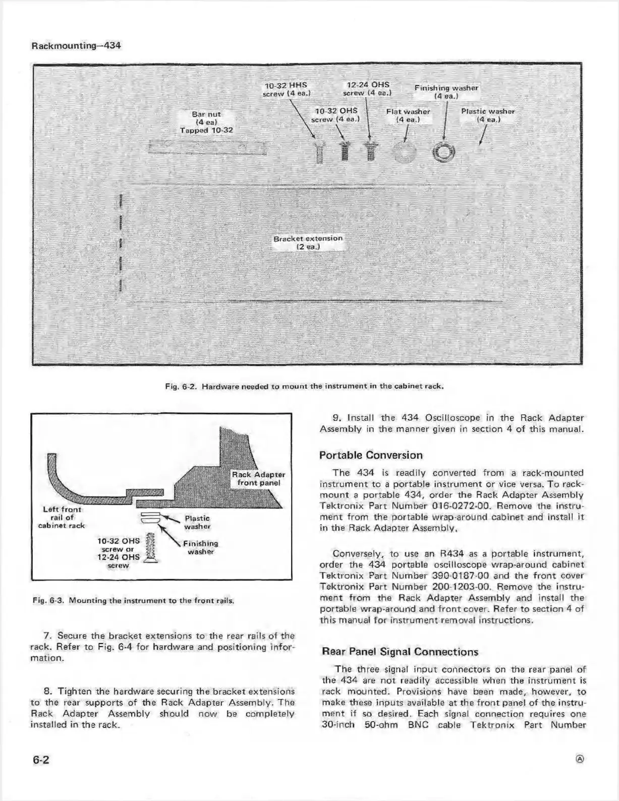
Fig. 6-3. M o u n tin g the in s tru m e n t to th e fro n t rails.
7. Secure the bracket extensions to the rear rails o f the
rack. Refer to Fig. 6-4 fo r hardware and positioning in fo r
m ation.
8. Tighten the hardware securing the bracket extensions
to the rear supports o f the Rack A dapter Assembly. The
Rack Adapter Assembly should nov\' be com pletely
installed in the rack.
9. Install the 434 O scilloscope in the Rack Adapter
Assem bly in the manner given in section 4 of this manual.
Portable Conversion
The 434 is readily converted fro m a rack-m ounted
instrum ent to a portable instrum e nt or vice versa. To rack-
m ount a portable 434, order the Rack A dapter Assembly
T e k tron ix Part N um ber 016-0272-00. Remove the instru
m ent from the portable w rap-around cabinet and install it
in the Rack A dapter Assembly.
Conversely, to use an R434 as a portable instrum ent,
order the 434 portable oscilloscope w rap-around cabinet
T e ktron ix Part N um ber 390-0187-00 and the fro n t cover
T e k tro n ix Part Num ber 200-1203-00. Remove the in stru
m ent fro m the Rack Ad apter Assembly and install the
portable wrap-around and fro n t cover. Refer to section 4 of
this manual fo r instrum en t removal instructions.
Rear Panel Signal Connections
The three signal in p ut connectors on the rear panel of
the 434 are no t readily accessible when the instrum ent is
rack m ounted. Provisions have been made, however, to
make these inputs available at the fro n t panel o f the in stru
m ent if so desired. Each signal connection requires one
30-inch 50-ohm BNC cable T e ktro n ix Part Num ber
6-2
 Loading...


