Calibration—434
21. Check CH 2 Variable VO LTS/DIV Range and
Attenuator Accuracy
a. Remove the Standard A m plitude Calibrator signal
from the CH 1 input connector and connect it to the CH 2
input connector and set the Vertical Mode to CH 2.
b. W ith the CH 2 VO LTS/DIV switch set to 10 mV, set
the Standard A m plitude Calibrator fo r a 50 m illivolt output
signal amplitude.
c. W ith an exactly 5-division amplitude display, rotate
the CH 2 Variable V O LTS/D IV control.
d. CHECK—CRT display can be reduced in amplitude to
two divisions or less.
e. Set the CH 2 Variable VO LTS /D IV control to CAL.
f. CHECK—Using the CH 2 VO LTS /DIV switch and the
Standard Am plitude Calibrator settings given in Table 5-1,
check to see if the vertical deflection factor accuracy for
each position of the CH 2 VO LTS/DIV switch is w ithin 3%.
22. Check ADD Mode Operation
a. A pply the Standard Am plitude Calibrator output
signal to both the CH 1 and CH 2 input connectors via a
BNC T and tw o 42-inch 50 SI BNC cables.
b. Set both VO LTS/DIV switches to .1 V and the Ver
tical Mode to ADD.
c. Set the Standard Am plitude Calibrator fo r a .2 volt
output signal.
d. CHECK—CRT display fo r 4 divisions, ±0.12 division
of deflection.
e. Disconnect all test equipment.
23. Adjust Channel 1 VO LTS/DIV Switch Com
pensation
a. Set the Channel 1 V O LTS /D IV switch to 10 mV, the
Vertical Mode to CH 1, and the CH 1 Input Coupling to
DC.
b. Connect the high-amplitude output o f the Square-
Wave Generator (Type 106) to the CH 1 input connector
via a GR to BNC adapter, a 42-inch 50 SI BNC cable, a 50
SI BNC 10X attenuator, a 50 SI BNC termination, and a 24
picofarad input normalizer.
c. Adjust the output of the Square-Wave Generator fo r a
display five divisions in amplitude and a repetition rate of
one kilohertz.
d. Adjust the TRIGGER LEVEL control fo r a stable
display.
e. CH E C K-C R T display at each Channel 1 VO LTS/DIV
switch position for optimum square corner and fla t top.
Typically less than +2%, —2%, or a total of 2% peak to peak
aberration (+3%, —3%, or total of 3% peak to peak if the
measurement is being made outside of the +20°C to +30°C
temperature range). Remove the 10X attenuator and the 50
£2 BNC term ination as necessary to maintain a five-division
display amplitude.
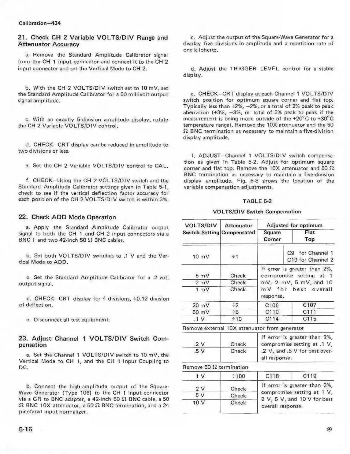
f. ADJU ST—Channel 1 VO LTS/D IV switch compensa
tion as given in Table 5-2. Adjust fo r optimum square
corner and flat top. Remove the 10X attenuator and 50 £2
BNC term ination as necessary to maintain a five-division
display amplitude. Fig. 5-8 shows the location of the
variable compensation adjustments.
TABLE 5-2
VO LTS/D IV Switch Compensation
VO LTS /D IV
Switch Setting
Attenuator
Adjusted fo r optimum
Compensated Square
Corner
Flat
Top
10 mV ±1
C9 for Channel 1
C19 for Channel 2
5 mV Check
If error is greater than 2%,
com prom ise setting at 1
mV, 2 mV, 5 m V, and 10
m V fo r best o v e ra ll
response.
2 mV Check
1 mV
Check
20 mV
-±2 C l 06 | C l07
50 mV ±■5
C110 j C111
.1 v
±10
Cl 14 C l 15
Remove external 10X attenuator from generator
.2 V
Check
If error is greater than 2%,
compromise setting at .1 V,
.2 V, and .5 V fo r best over
all response.
.5 V
Check
Remove 50 SI termination
1 V
±100 C l 18 Cl 19
2 V Check
If error is greater than 2%,
5 V
Check
compromise setting at 1 V,
2 V, 5 V, and 10 V for best
overall response.
10 V
Check
5-16