Calibration—434
Fig. 5-2. C urre nt waveform in collecto r c irc u it o f Q1080.
e. Set the sensitivity of the Current Probe Passive Ter
mination to 10 m A/m V and the Volts/Div switch of the
test oscilloscope to 50 mV/div.
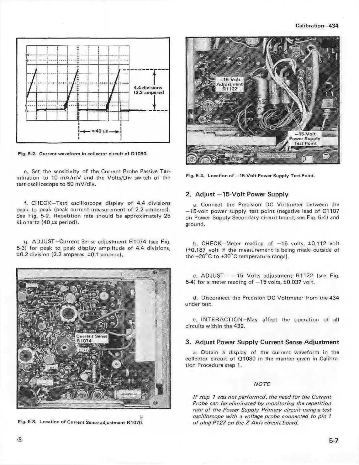
Fig, 5-4. Lo ca tion o f —15-V o lt Power S upply Test Point.
f. CHECK—Test oscilloscope display of 4.4 divisions
peak to peak (peak current measurement of 2.2 amperes).
See Fig. 5-2. Repetition rate should be approximately 25
kilohertz (40 /us period).
2. A d ju s t-1 5 -V o lt Power Supply
a. Connect the Precision DC Voltmeter between the
-1 5 -vo lt power supply test point (negative lead of C l 107
on Power Supply Secondary circuit board; see Fig. 5-4) and
ground.
g. ADJU S T-C urrent Sense adjustment R 1074 (see Fig. b CHECK-M eter reading of -1 5 volts, ±0.112 volt
5-3) for peak to peak display am plitude of 4.4 divisions, (±0.187 volt if the measurement is being made outside of
±0.2 division (2.2 amperes, ±0.1 ampere). the +20°C to ±30°C temperature range).
Fig. 5-3. Location o f C urre nt Sense ad justm ent R1070.
c. ADJUST— —15 Volts adjustment R1122 (see Fig.
5-4) fo r a meter reading o f —15 volts, ±0.037 volt.
d. Disconnect the Precision DC Voltmeter from the 434
under test.
e. INTE RA CTIO N—May affect the operation of all
circuits w ithin the 432.
3. Adjust Power Supply Current Sense Adjustment
a. Obtain a display of the current waveform in the
collector circuit of Q1080 in the manner given in Calibra
tion Procedure step 1.
NOTE
i f step 1 was n ot perform ed, the need fo r the Current
Probe can be eliminated by m onitoring the repetition
rate o f the Power Supply Primary circuit using a test
oscilloscope with a voltage probe connected to pin 1
o f plug P i 27 on the Z Axis circu it board.
®
5-7
 Loading...


