Circuit Description—434
stage does not make available a sample of the Channel 2
signal for triggering use. Also, INVERT switch S414 has
been added in the Channel 2 circuit. This switch allows the
displayed signal from Channel 2 to be inverted.
CHANNEL SWITCH
General
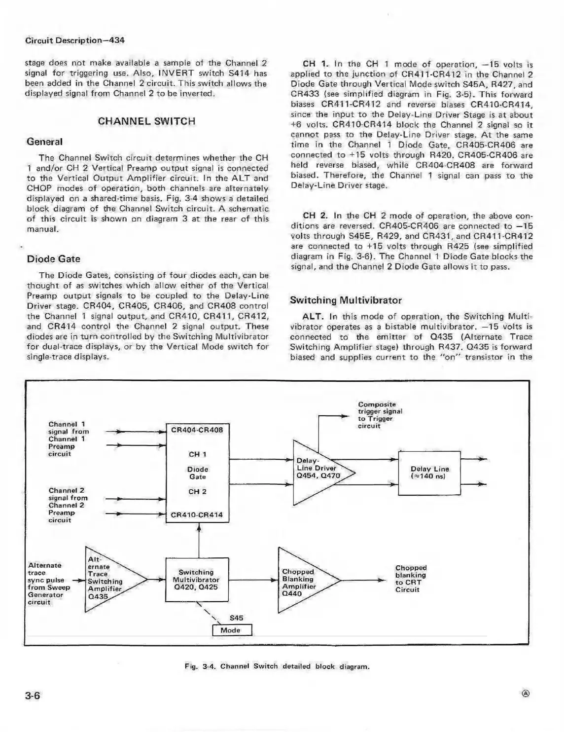
The Channel Switch circuit determines whether the CH
1 and/or CH 2 Vertical Preamp output signal is connected
to the Vertical O utput Am plifier circuit. In the ALT and
CHOP modes of operation, both channels are alternately
displayed on a shared-time basis. Fig. 3-4 shows a detailed
block diagram of the Channel Switch circuit. A schematic
of this circuit is shown on diagram 3 at the rear of this
manual.
Diode Gate
The Diode Gates, consisting of four diodes each, can be
thought of as switches which allow either o f the Vertical
Preamp output signals to be coupled to the Delay-Line
Driver stage. CR404, CR405, CR406, and CR408 control
the Channel 1 signal output, and CR410, CR411, CR412,
and CR414 control the Channel 2 signal output. These
diodes are in turn controlled by the Switching M ultivibrator
fo r dual-trace displays, or by the Vertical Mode switch for
single-trace displays.
CH 1. In the CH 1 mode of operation, —15 volts is
applied to the junction of CR411-CR412 in the Channel 2
Diode Gate through Vertical Mode switch S45A, R427, and
CR433 (see simplified diagram in Fig. 3-5). This forward
biases CR411-CR412 and reverse biases CR410-CR414,
since the input to the Delay-Line Driver Stage is at about
+6 volts. CR410-CR414 block the Channel 2 signal so it
cannot pass to the Delay-Line Driver stage. A t the same
tim e in the Channel 1 Diode Gate, CR405-CR406 are
connected to +15 volts through R420. CR405-CR406 are
held reverse biased, while CR404-CR408 are forward
biased. Therefore, the Channel 1 signal can pass to the
Delay-Line Driver stage.
CH 2. In the CH 2 mode of operation, the above con
ditions are reversed. CR405-CR406 are connected to —15
volts through S45E, R429, and CR431, and CR411-CR412
are connected to +15 volts through R425 (see simplified
diagram in Fig. 3-6). The Channel 1 Diode Gate blocks the
signal, and the Channel 2 Diode Gate allows it to pass.
Switching Multivibrator
A LT . In this mode of operation, the Switching M ulti
vibrator operates as a bistable m ultivibrator. —15 volts is
connected to the emitter of Q435 (Alternate Trace
Switching Am plifier stage) through R437. Q435 is forward
biased and supplies current to the “ o n " transistor in the
C om p os ite
3-6
Fig. 3-4. Channel S w itch detailed block diagram .
 Loading...


