Operating Instructions—434
3. Set the V O LT S /D IV switch and Variable control to
produce a display exactly six divisions in amplitude.
Substituting the given values:
Risetime = 6 X 1 (is
4. Center the display about the center horizontal line
w ith the vertical POSITION control.
The risetime is 6 microseconds.
5. Set the TRIG G ER IN G controls to obtain a stable
display.
6. Set the T IM E /D IV switch to the fastest sweep rate
tha t w ill display less than eight divisions between the 10%
and 90% points on the waveform .
Time Difference Measurements
The calibrated sweep rate and dual-trace features of the
434 allow measurement of tim e difference between tw o
separate events. To measure time difference use the fo llo w
ing procedure:
7. Adjust the horizontal POSITION control to move the
10% po int o f the waveform to the second vertical line of
the graticule (see Fig. 2-10).
8. Measure the horizontal distance between the 10% and
90% points. Be sure the Variable T IM E /D IV control is set
to C AL.
9. M ultip ly the distance measured in step 8 by the
setting of the T IM E /D IV switch.
1. Set the Inpu t Coupling switches to the same position,
depending on the type of coupling desired.
2. Set the Vertical Mode switch to either CHOP or A LT .
In general, CHOP is m ore suitable fo r low-frequency signals
and the A LT position is more suitable fo r high-frequency
signals. More inform ation on determ ining the mode is given
under Dual-Trace Operation in this section.
3. Set the TRIGG ER SOURCE switch to CH 1.
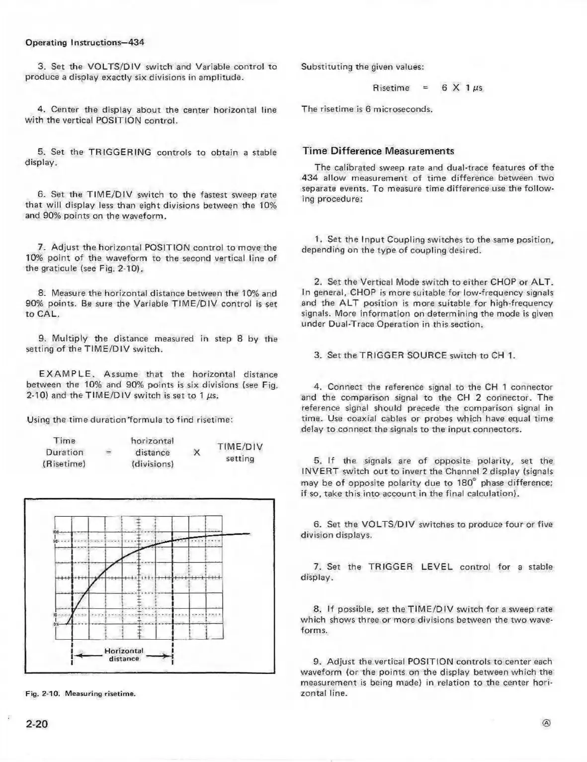
E X A M P L E . Assume that the horizontal distance
between the 10% and 90% points is six divisions (see Fig.
2-10) and the T IM E /D IV switch is set to 1 jus.
Using the tim e dura tion'form ula to find risetime:
Tim e
Duration
(Risetime)
horizontal
distance
(divisions)
T IM E /D IV
setting
Fig. 2-10. M easuring risetime.
4. Connect the reference signal to the CH 1 connector
and the comparison signal to the CH 2 connector. The
reference signal should precede the comparison signal in
time. Use coaxial cables or probes which have equal time
delay to connect the signals to the in put connectors.
5. If the signals are of opposite polarity, set the
IN VE R T switch out to invert the Channel 2 display (signals
may be o f opposite polarity due to 18CT phase difference;
if so, take this into account in the final calculation).
6. Set the V O LT S /D IV switches to produce fo ur or five
division displays.
7. Set the TRIGG ER LE VE L control fo r a stable
display.
8. If possible, set the T IM E /D IV switch fo r a sweep rate
which shows three or more divisions between the tw o wave
forms.
9. Adjust the vertical POSITION controls to center each
waveform (or the points on the display between which the
measurement is being made) in relation to the center ho ri
zontal line.
2-20
 Loading...


