Operating Instructions—434
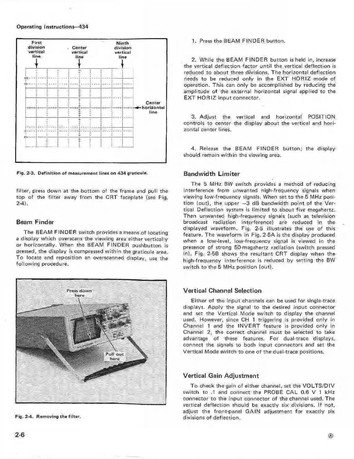
First N in th
division . cen ter division
vertical vertical vertical
line line line
4
4
1
1
{
j
Center
•
:
....
....
:
: :
1
....
line
• .
• r
’ i 1
1. Press the BEAM F INDER button.
2. While the BEAM FINDER button is held in, increase
the vertical deflection factor until the vertical deflection is
reduced to about three divisions. The horizontal deflection
needs to be reduced only in the EXT HORIZ mode of
operation. This can only be accomplished by reducing the
amplitude of the external horizontal signal applied to the
EXT HORIZ input connector.
3. Adjust the vertical and horizontal POSITION
controls to center the display about the vertical and hori
zontal center lines.
4. Release the BEAM FINDER button; the display
should remain w ithin the viewing area.
Fig. 2-3. D e fin itio n o f measurement lines on 43 4 graticule.
filter, press down at the bottom of the frame and pull the
top of the filter away from the CRT faceplate (see Fig.
2-4).
Beam Finder
The BEAM' F INDER switch provides a means of locating
a display which overscans the viewing area either vertically
or horizontally. When the BEAM FINDER pushbutton is
pressed, the display is compressed w ithin the graticule area.
To locate and reposition an overscanned display, use the
following procedure.
Bandwidth Limiter
The 5 MHz BW switch provides a method of reducing
interference from unwanted high-frequency signals when
viewing low-frequency signals. When set to the 5 MHz posi
tion (out), the upper —3 dB bandwidth point of the Ver
tical Deflection system is limited to about five megahertz.
Then unwanted high-frequency signals (such as television
broadcast radiation interference) are reduced in the
displayed waveform. Fig. 2-5 illustrates the use of this
feature. The waveform in Fig. 2-5A is the display produced
when a low-level, low-frequency signal is viewed in the
presence of strong 50-megahertz radiation (switch pressed
in). Fig. 2-5B shows the resultant CRT display when the
high-frequency interference is reduced by setting the BW
switch to the 5 MHz position (out).
Fig. 2-4. Rem oving the filte r.
Vertical Channel Selection
Either of the input channels can be used fo r single-trace
displays. A pply the signal to the desired input connector
and set the Vertical Mode switch to display the channel
used. However, since CH 1 triggering is provided only in
Channel 1 and the INVER T feature is provided only in
Channel 2, the correct channel must be selected to take
advantage of these features. For dual-trace displays,
connect the signals to both input connectors and set the
Vertical Mode switch to one of the dual-trace positions.
Vertical Gain Adjustment
To check the gain of either channel, set the VO LTS/D IV
switch to .1 and connect the PROBE CAL 0.6 V 1 kHz
connector to the input connector of the channel used. The
vertical deflection should be exactly six divisions. If not,
adjust the front-panel GAIN adjustment fo r exactly six
divisions of deflection.
2-6
 Loading...


