Calibration—434
POWER SUPPLY AND DISPLAY
Equipment Required
1. Test Oscilloscope
7. Current Probe
2. Medium-Frequency Constant-Am plitude Signal
8. Adapter (GR874 and BNC female connectors)
Generator
3. Time-Mark Generator
4. Precision DC Voltmeter
5. DC Voltmeter
6. Autotransform er
9. 50 El BNC Term ination
10. 42-Inch 50 £2 BNC Cables (2 ea.)
11. BNC T Connector
12. 3-Inch Screwdriver
Control Settings
Preset instrument controls to the settings given under
Preliminary Control Settings.
1. Preset Power Supply Current Sense Adjustment
NOTE
This step need be performed only if the setting o f
R1074 has become grossly misad/usted, or if major
circuit components in the pow er supply have been
replaced that w ould cause the setting o f R 1074 to be
incorrect, i f the power supply portion of this
instrum ent has been working correctly, proceed w ith
step 2.
a. Turn o ff instrument power, disconnect the power
line, and remove the power supply compartment shields to
provide access to leads connected to transistor Q1080. See
Fig. 5-1.
Under certain conditions. C l016 can remain charged
fo r several minutes. I f one o f the two neon bulbs on
the Primary Power Supply circuit board is s till lit
with instrum ent power turned o ff, wait u ntil both
lights are extinguished before attem pting to discharge
C l016 and/or w orking in the power supply area.
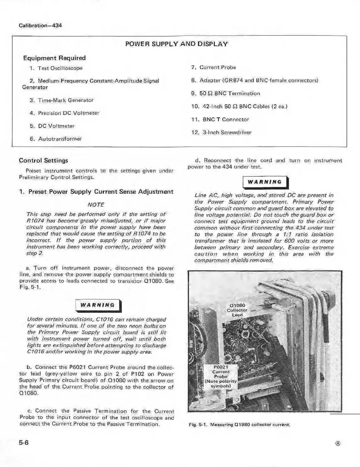
b. Connect the P6021 Current Probe around the collec
tor lead (grey-yellow wire to pin 2 of P I02 on Power
Supply Primary circuit board) of Q1080 w ith the arrow on
the head of the Current Probe pointing to the collector of
Q1080.
c. Connect the Passive Termination for the Current
Probe to the input connector of the test oscilloscope and
connect the Current Probe to the Passive Termination.
d. Reconnect the line cord and turn on instrument
power to the 434 under test.
WARNING I
Line AC, high voltage, and stored DC are present in
the Power Supply compartment. Primary Power
Supply c ircuit common and guard box are elevated to
line voltage potential. Do n o t touch the guard box or
connect test equipm ent ground leads to the circuit
common w ithout first connecting the 434 under test
to the power tine through a 1:1 ratio isolation
transformer that is insulated for 600 volts or more
between prim ary and secondary. Exercise extreme
caution when working in this area with the
compartment shields removed.
a loso
C ollector
Lead
P6021
Current
Probe
(N ote p o la rity
sym bols)
Fig. 5-1. Measuring Q 1980 co llector current.
5-6
 Loading...


