SECTION 6
RACKMOUNTING
434
Change info rm atio n, i f any, affecting this section w ill be fou nd a t the rear o f this manual.
Introduction
The Te ktronix R434 Oscilloscope is designed to m ount
in a standard 19-inch rack. When mounted in accordance
w ith the following mounting procedure this instrum ent w ill
meet all electrical and environm ental characteristics given in
section 1.
Rack Dimensions
Height. A t least 5 1/4 inches of vertical space is required
to m ount this instrum ent in a rack.
W idth. Minimum w idth of the opening between the left
and right fro n t rails o f the rack must be 17 5/8 inches.
Depth. Total depth necessary to m ount the R434 in a
cabinet rack is 18 inches. This allows room fo r air circula
tion , power cord connection and the necessary m ounting
hardware.
Mounting Procedure
The fo llow ing m ounting procedure uses the Rack
Adapter Assembly and the included R ackm ount Hardware
K it to insure meeting the environmental characteristics of
the instrum ent. If alternative methods of mounting are
used, the instrum ent may no t meet the given environm ental
characteristics fo r shock and vibration.
Use the follow ing procedure to install the R434 in a
rack:
1. Remove the instrum ent from the Rack Adapter
Assembly in the manner given fo r cabinet removal in
section 4 of this manual.
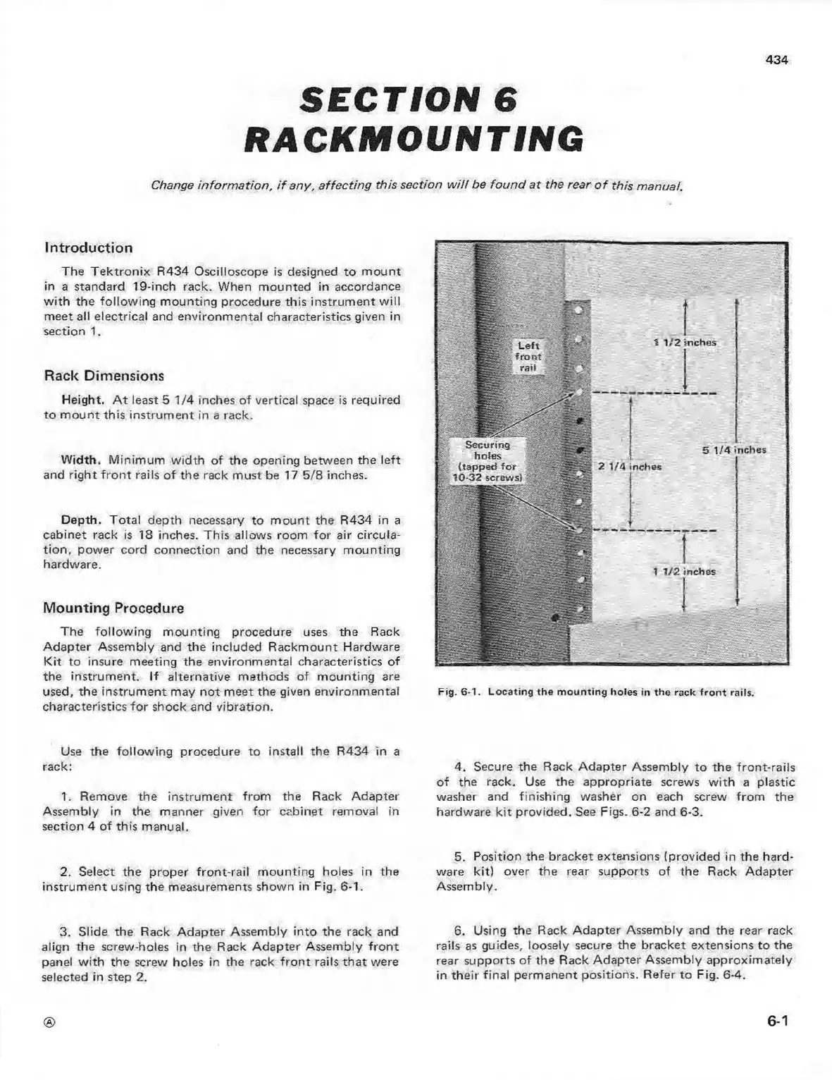
2. Select the proper fron t-rail m ounting holes in the
instrum ent using the measurements shown in Fig. 6-1.
3. Slide the Rack Adapter Assembly into the rack and
align the screw-holes in the Rack Adapter Assembly fro n t
panel w ith the screw holes in the rack fro n t rails that were
selected in step 2.
Fig. 6-1. Locatin g the m ountin g holes in th e rack fro n t rails.
4. Secure the Rack Adapter Assembly to the front-rails
of the rack. Use the appropriate screws w ith a plastic
washer and finishing washer on each screw from the
hardware kit provided. See Figs. 6-2 and 6-3.
5. Position the bracket extensions (provided in the hard
ware kit) over the rear supports of the Rack Adapter
Assembly.
6. Using the Rack A dapter Assembly and the rear rack
rails as guides, loosely secure the bracket extensions to the
rear supports of the Rack Adapter Assembly approxim ately
in their final permanent positions. Refer to Fig. 6-4.
6-1
 Loading...


