Operating Instructions—434
Fig. 2-12. Measuring phase d ifferen ce.
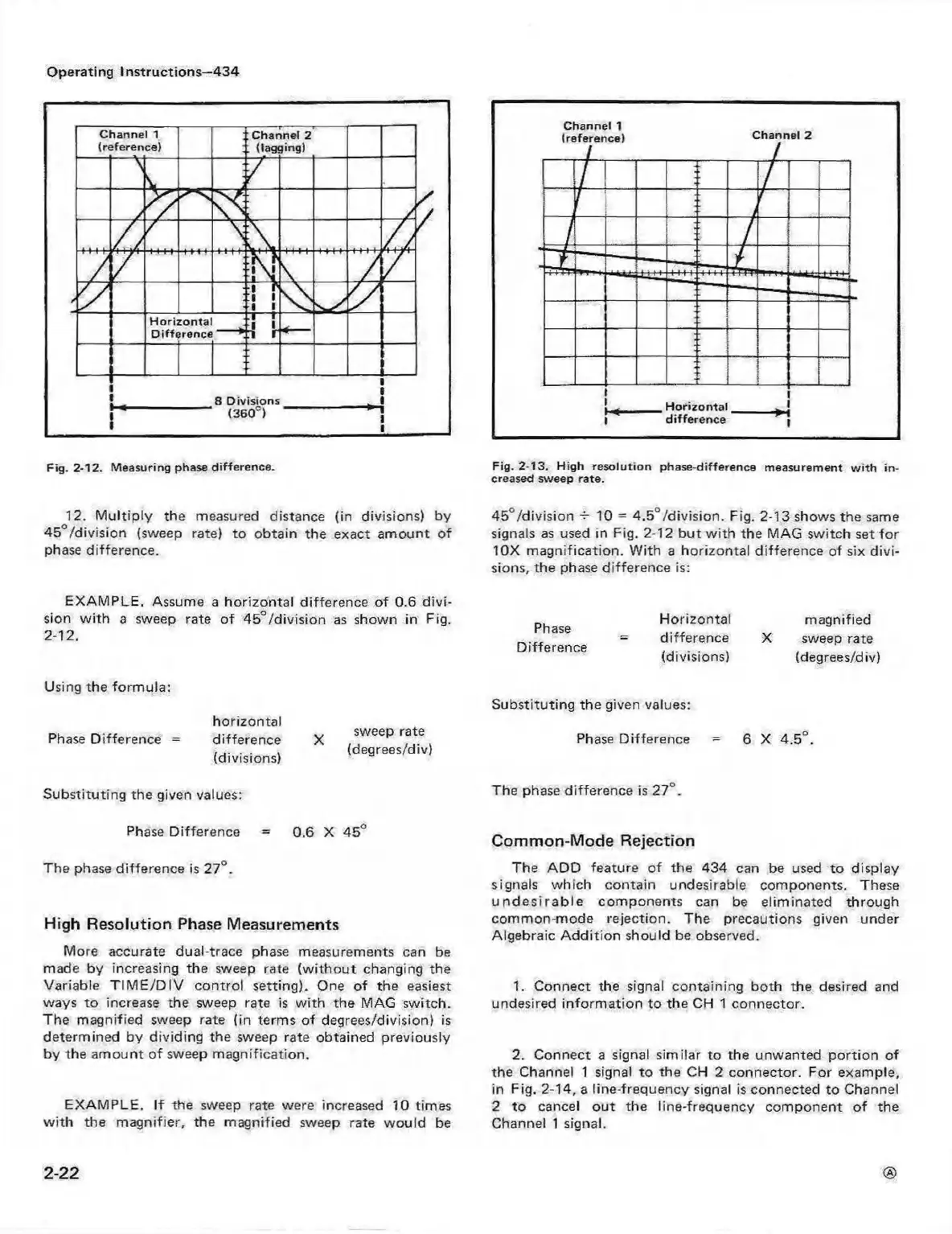
Fig. 2-13. H igh re solution phase-differe nce measurem ent w ith in
creased sweep rate.
12. M ultip ly the measured distance (in divisions) by
45 °/division (sweep rate) to obtain the exact am ount of
phase difference.
45 °/division -5- 10 = 4.5°/division. Fig. 2-13 shows the same
signals as used in Fig. 2-12 but w ith the MAG switch set fo r
10X m agnification. W ith a horizontal difference of six divi
sions, the phase difference is:
EXAM PLE. Assume a horizontal difference of 0.6 divi
sion w ith a sweep rate of 45 °/division as shown in Fig.
2- 12.
Phase
Difference
Horizontal
difference
(divisions)
magnified
X sweep rate
(degrees/div)
Using the form ula:
Phase Difference =
horizontal
difference
(divisions)
sweep rate
(degrees/div)
Substituting the given values:
Phase Difference = 6 X 4.5°.
Substituting the given values:
The phase difference is 27°.
Phase Difference = 0.6 X 45°
Common-Mode Rejection
The phase difference is 27°.
High Resolution Phase Measurements
More accurate dual-trace phase measurements can be
made by increasing the sweep rate (w ith ou t changing the
Variable T IM E /D IV control setting). One o f the easiest
ways to increase the sweep rate is w ith the MAG switch.
The magnified sweep rate (in terms of degrees/division) is
determined by dividing the sweep rate obtained previously
by the am ount of sweep magnification.
EXAM PLE. If the sweep rate were increased 10 times
w ith the m agnifier, the magnified sweep rate w ould be
The AD D feature o f the 434 can be used to display
signals w hich contain undesirable components. These
u n d e s ira b le components can be elim inated through
common-mode rejection. The precautions given under
Algebraic A ddition should be observed.
1. Connect the signal containing both the desired and
undesired inform ation to the CH 1 connector.
2. Connect a signal similar to the unwanted portion of
the Channel 1 signal to the CH 2 connector. For example,
in Fig. 2-14, a line-frequency signal is connected to Channel
2 to cancel out the line-frequency component of the
Channel 1 signal.
2-22
 Loading...


