Calibration—434
e. Set the CH 2 VO LTS/D IV switch to 10 mV.
f. Rotate the CH 2 Variable V O LTS/D IV control.
g. CHECK—CRT display for not more than 0.2 division
of trace shift when rotating the CH 2 Variable V O LTS /D IV
control.
h. ADJU ST—Variable Balance adjust R312 (see Fig.
5-7) for minimum trace shift when rotating the CH 2
Variable V O LTS /D IV control.
i. Set the CH 2 VO LTS /DIV switch to 10 m V and the
CH 2 Variable VO LTS/D IV control to CAL.
j. Position the free-running trace to the center hori
zontal graticule line.
k. Set the INVER T switch to the INVERT position
(button out).
I. CHECK—CRT display for not more than 0.2 division
of trace shift when inverting the Channel 2 display.
m. ADJUST—Invert Balance adjustment R348 (see Fig.
5-7) for m inimum trace shift when inverting the Channel 2
display.
n. Push the INVERT button in.
19. Adjust CH 1 and CH 2 GAIN
a. Set input coupling for both channels to DC.
b. Connect the output of the Standard Am plitude Cali
brator to the CH 2 input connector via a 42-inch BNC
cable.
c. Set the Standard Am plitude Calibrator for a 50 m illi
volt signal output amplitude.
d. CHECK—CRT display for 5 divisions, ±0.15 division
of deflection.
e. ADJUST—CH 2 GAIN adjustment (located on fro n t
panel) for exactly 5 divisions of deflection.
f. Change Vertical Mode to CH 1.
g. Remove the Standard Am plitude Calibrator signal
from the CH 2 input connector and connect it to the CH 1
input connector.
h. CHECK—CRT display for 5 divisions, ±0.15 division
of deflection.
i. ADJUST—CH 1 GAIN adjustment (located on fro nt
panel) for exactly 5 divisions of deflection.
20. Check CH 1 Variable VO LTS/D IV Range and
Attenuator Accuracy
a. With exactly a 5-division amplitude display, rotate
the CH 1 Variable V O LTS/D IV control.
b. CHECK—CRT display can be reduced in amplitude to
two divisions or less.
c. Set the CH 1 Variable VO LTS/D IV control to CAL.
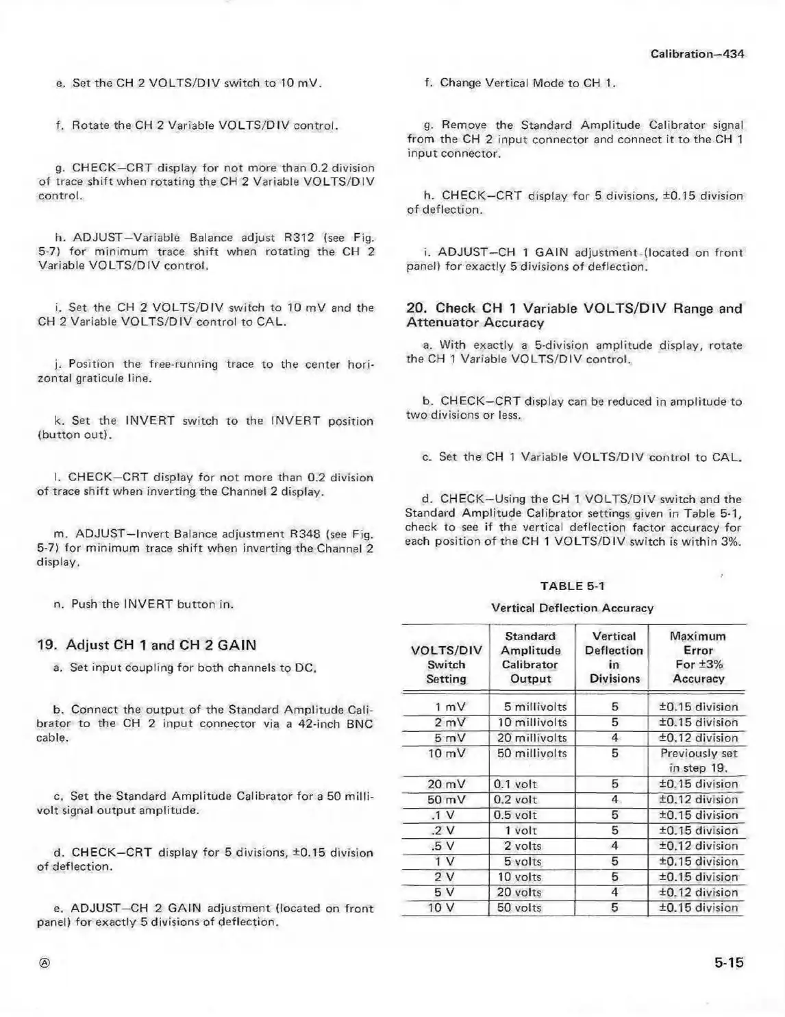
d. CHECK—Using the CH 1 V O LTS/DIV switch and the
Standard Am plitude Calibrator settings given in Table 5-1,
check to see if the vertical deflection factor accuracy for
each position o f the CH 1 VO LTS/DIV switch is w ithin 3%.
TABLE 5-1
Vertical Deflection Accuracy
VO LTS /D IV
Switch
Setting
Standard
Am plitude
Calibrator
Output
Vertical
Deflection
in
Divisions
Maximum
Error
For +3%
Accuracy
1 mV
5 m illivolts
5
±0.15 division
2 mV
10 m illivolts
5
±0.15 division
5 mV 20 m illivolts
4
±0.12 division
10 mV 50 m illivolts 5
Previously set
in step 19.
20 mV 0.1 volt
5
±0.15 division
50 mV 0.2 volt
4 ±0.12 division
.1 V
0.5 volt 5
±0.15 division
.2 V 1 volt 5 ±0.15 division
.5 V 2 volts
4 ±0.12 division
1 V
5 volts 5 ±0.15 division
2 V 10 volts 5 ±0.15 division
5 V 20 volts 4
±0.12 division
10 V 50 volts 5
±0.15 division
5-15
 Loading...


