Calibration—434
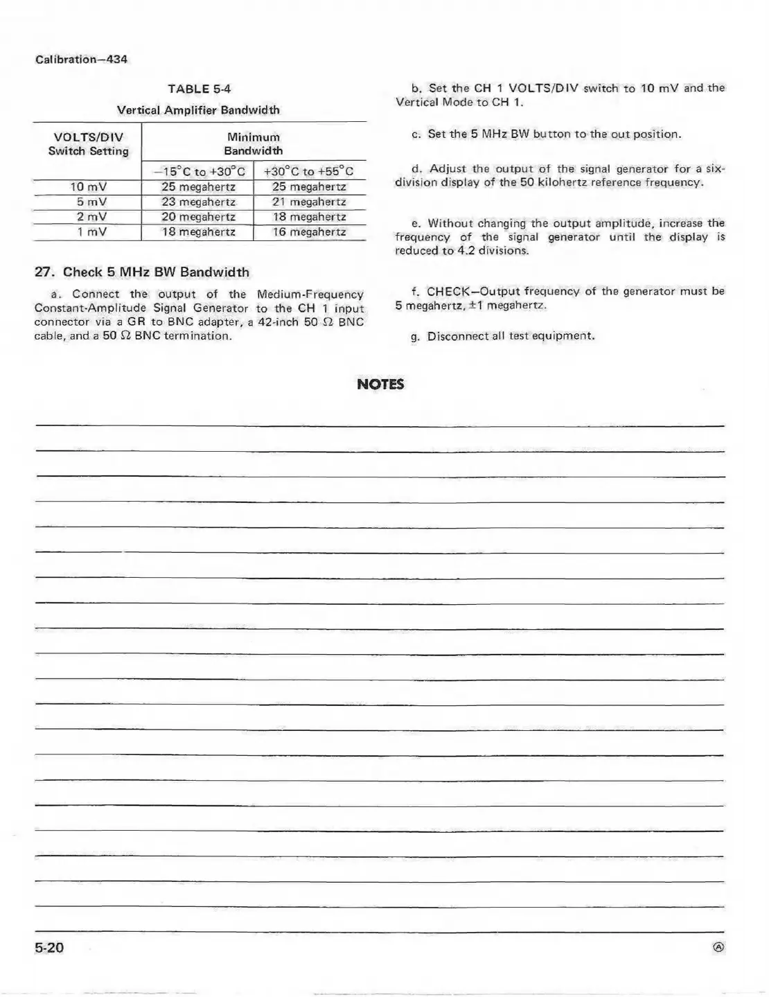
TABLE 5-4
Vertical Amplifier Bandwidth
VOLTS/DIV
Minimum
Switch Setting
Bandwidth
— 15; C to +30°C
+30°C to +55°C
10 mV 25 megahertz
25 megahertz
5 mV
23 megahertz
21 megahertz
2 mV 20 megahertz 18 megahertz
1 mV 18 megahertz 16 megahertz
27. Check 5 MHz BW Bandwidth
a. Connect the output of the Medium-Frequency
Constant-Amplitude Signal Generator to the CH 1 input
connector via a GR to BNC adapter, a 42-inch 50 H BNC
cable, and a 50 £1 BNC termination.
b. Set the CH 1 VOLTS/DIV switch to 10 mV and the
Vertical Mode to CH 1.
c. Set the 5 MHz BW button to the out position.
d. Adjust the output of the signal generator for a six-
division display of the 50 kilohertz reference frequency.
e. W ithout changing the output amplitude, increase the
frequency of the signal generator until the display is
reduced to 4.2 divisions.
f. CHECK—Output frequency of the generator must be
5 megahertz, +1 megahertz.
g. Disconnect all test equipment.
NOTES
 Loading...


