SECTION 8
DIAGRAMS, CIRCUIT BOARDS, MECHANICAL
AND REPACKAGING PARTS ILLUSTRATIONS
434
Symbols and Reference Designators
Electrical com ponents show n on the diagram s are in th e fo llo w in g u nits unless noted otherw ise:
Capacitors = Values one o r greater are in picofarads (pF).
Values less than one are in m icrofarads (m F).
Resistors = O hm s ( fi)
Sym bols used on the diagrams are based on USA S tandard Y 32.2-1967.
Logic sym bology is based on M IL-S TD -806B in term s o f positive logic. Logic sym bols d e p ic t the logic fu n c tio n perform ed
and may d iffe r fro m the m an ufa cturer's data.
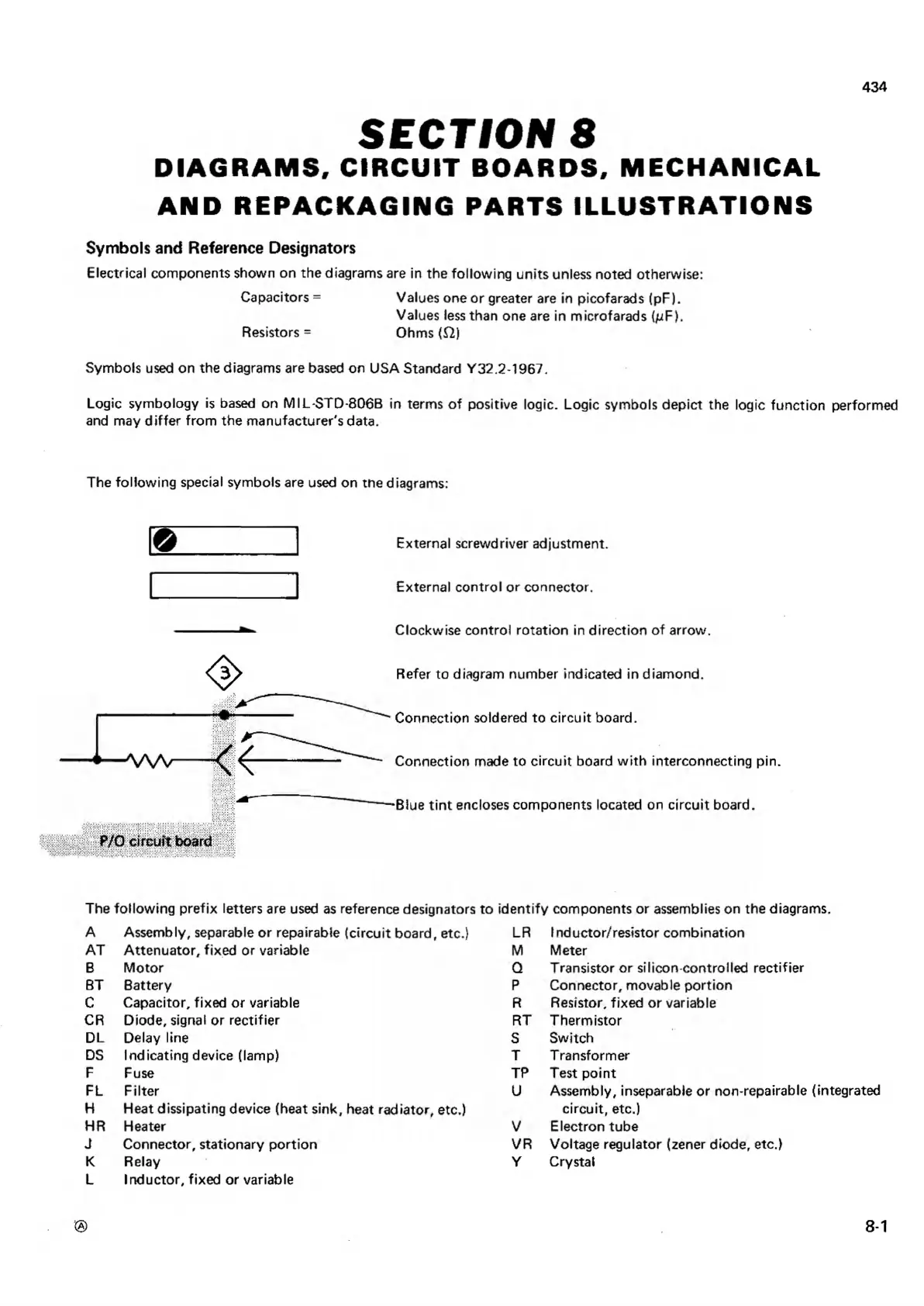
The fo llo w in g special sym bols are used on tne diagram s:
<3>
E xternal screwdriver adjustm ent.
E xtern al c o n tro l o r connector.
C lockw ise contro l ro ta tio n in d ire ctio n o f arrow .
Refer to diagram num ber indicated in diam o nd.
C onnection soldered to c irc u it board.
C onnection made to c irc u it board w ith interconnecting pin.
Blue tin t encloses com ponents located on c irc u it board.
The fo llo w in g p re fix letters are used as reference designators to id e n tify com ponents or assemblies on th e diagrams.
A Assem bly, separable o r repairable (c irc u it board, etc.)
A T A tte n u a to r, fix e d o r variable
B M o to r
BT Battery
C C apacitor, fixe d o r variable
CR D iode, signal o r rectifie r
DL D elay line
DS In dicatin g device (lam p)
F Fuse
FL F ilte r
H Heat dissipating device (heat sink, heat rad ia tor, etc.)
HR Heater
J Connector, statio n a ry p o rtio n
K Relay
L In d u cto r, fixe d or variable
LR I nd uctor/resistor com bination
M M eter
Q Transistor o r silicon-contro lle d re c tifie r
P C o n n ector, movable po rtio n
R R esistor, fixe d or variable
RT T h e rm istor
S S w itch
T T ransform er
TP Test p o in t
U A ssem bly, inseparable o r non-repairable (integrated
circ u it, etc.)
V E lectron tube
VR V oltage regulator (zener diode, etc.)
Y Crystal
8-1
 Loading...


