C ircuit Description—434
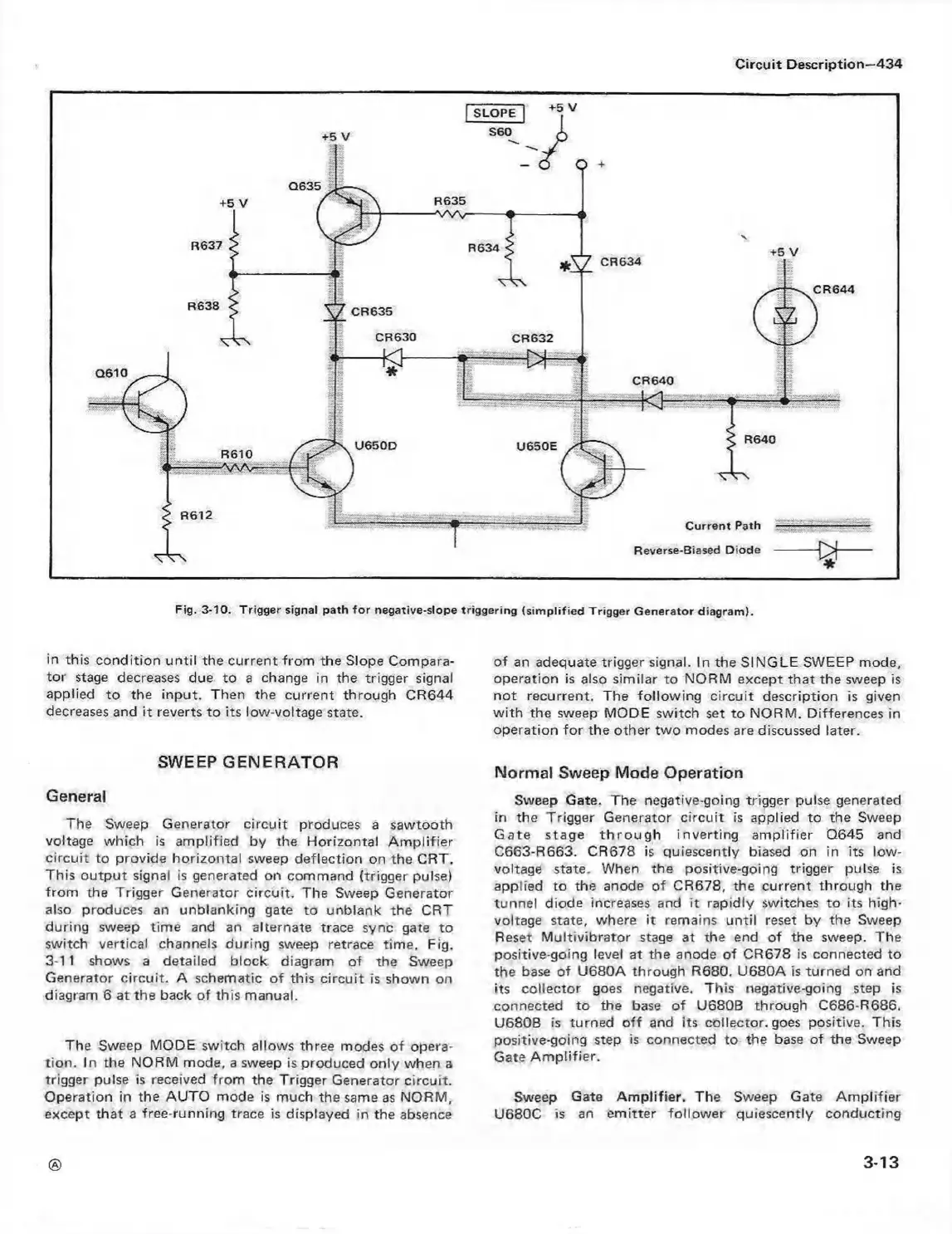
Fig. 3-10. Trigger signal path fo r negative-slope triggering (sim plifie d Trigger Generator diagram ).
in this condition until the current from the Slope Compara
tor stage decreases due to a change in the trigger signal
applied to the input. Then the current through CR644
decreases and it reverts to its low-voltage state.
SWEEP GENERATOR
General
The Sweep Generator circuit produces a sawtooth
voltage which is amplified by the Horizontal Am plifier
circuit to provide horizontal sweep deflection on the CRT.
This output signal is generated on command (trigger pulse)
from the Trigger Generator circuit. The Sweep Generator
also produces an unblanking gate to unblank the CRT
during sweep time and an alternate trace sync gate to
switch vertical channels during sweep retrace time. Fig.
3-1 1 shows a detailed block diagram of the Sweep
Generator circuit. A schematic of this circuit is shown on
diagram 6 at the back of this manual.
The Sweep MODE switch allows three modes of opera
tion. In the NORM mode, a sweep is produced only when a
trigger pulse is received from the Trigger Generator circuit.
Operation in the AUTO mode is much the same as NORM,
except that a free-running trace is displayed in the absence
of an adequate trigger signal. In the SINGLE SWEEP mode,
operation is also similar to NORM except that the sweep is
not recurrent. The following circuit description is given
w ith the sweep MODE switch set to NORM. Differences in
operation fo r the other two modes are discussed later.
Normal Sweep Mode Operation
Sweep Gate. The negative-going trigger pulse generated
in the Trigger Generator circuit is applied to the Sweep
G ate stage th ro u g h inverting am plifier Q645 and
C663-R663. CR678 is quiescently biased on in its low-
voltage state. When the positive-going trigger pulse is
applied to the anode of CR678, the current through the
tunnel diode increases and it rapidly switches to its high-
voltage state, where it remains until reset by the Sweep
Reset Multivibrator stage at the end of the sweep. The
positive-going level at the anode of CR678 is connected to
the base of U680A through R680. U680A is turned on and
its collector goes negative. This negative-going step is
connected to the base of U680B through C686-R686.
U680B is turned o ff and its collector, goes positive. This
positive-going step is connected to the base of the Sweep
Gate Am plifier.
Sweep Gate Am plifier. The Sweep Gate Am plifier
U680C is an em itter follower quiescently conducting
3-13
 Loading...


