C ircuit Description—434
adjustment R629. The Trigger Level Centering adjustment
sets the level at the base of U650E so the display is
correctly triggered when the LEVEL control is centered.
The LEVEL control varies the base level of U650E to select
the point on the trigger signal where triggering occurs.
Diodes CR615 and CR616 prevent overdrive occurring in
the Slope Comparator. Q618 is a relatively constant current
source fo r U650D and U650E.
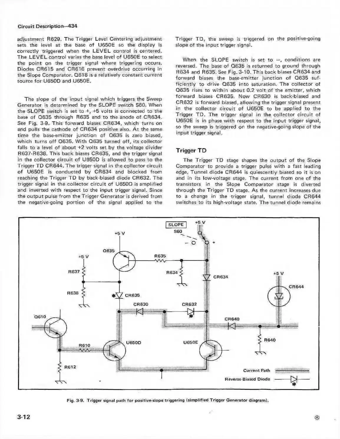
The slope of the input signal which triggers the Sweep
Generator is determined by the SLOPE switch S60. When
the SLOPE switch is set to +, +5 volts is connected to the
base of Q635 through R635 and to the anode o f CR634.
See Fig. 3-9. This forward biases CR634, which turns on
and pulls the cathode of CR634 positive also. A t the same
time the base-emitter junction of Q635 is zero biased,
which turns o ff Q635. With Q635 turned o ff, its collector
falls to a level of about +2 volts set by the voltage divider
R637-R638. This back biases CR635, and the trigger signal
in the collector circuit of U650D is allowed to pass to the
Trigger TD CR644. The trigger signal in the collector circuit
of U650E is conducted by CR634 and blocked from
reaching the Trigger TD by back-biased diode CR632. The
trigger signal in the collector circuit of U650D is amplified
and inverted with respect to the input trigger signal. Since
the output pulse from the Trigger Generator is derived from
the negative-going portion of the signal applied to the
Trigger TD, the sweep is triggered on the positive-going
slope of the input trigger signal.
When the SLOPE switch is set to —, conditions are
reversed. The base of Q635 is returned to ground through
R634 and R635. See Fig. 3-10. This back biases CR634 and
forward biases the base-emitter junction of Q635 suf
ficiently to drive Q635 into saturation. The collector of
Q635 rises to w ith in about 0.2 volt o f the em itter, which
forward biases CR635. Now CR630 is back-biased and
CR632 is forward biased, allowing the trigger signal present
in the collector circuit of U650E to be applied to the
Trigger TD. The trigger signal in the collector circuit of
U650E is in phase w ith respect to the input trigger signal,
so the sweep is triggered on the negative-going slope of the
input trigger signal.
Trigger TD
The Trigger TD stage shapes the output of the Slope
Comparator to provide a trigger pulse w ith a fast leading
edge. Tunnel diode CR644 is quiescently biased so it is on
and in its low-voltage stage. The current from one of the
transistors in the Slope Comparator stage is diverted
through the Trigger TD stage. As the current increases due
to a change in the trigger signal, tunnel diode CR644
switches to its high-voltage state. The tunnel diode remains
3-12
Fig. 3-9. Trigger signal path fo r positive-slope triggering (sim p lified Trigger G enerator diagram).
 Loading...


